How to Plan Safe Air Compressor Plumbing
For safe air compressor plumbing, choose pipe and fittings rated for compressed air, then size the main line for your tools’ combined airflow and the length of the run. Connect the compressor with a rated flexible hose to limit vibration. Slope the main toward a drain, take tool drops from the top of the line, and add tank and low-point drains. Do not use ordinary PVC or CPVC pipe for compressed air.
I’m Lance Vanover, CEO of Lynco Flange & Fitting. My 26 years in industrial pipe and fitting distribution inform this guide to choosing and installing air compressor plumbing.
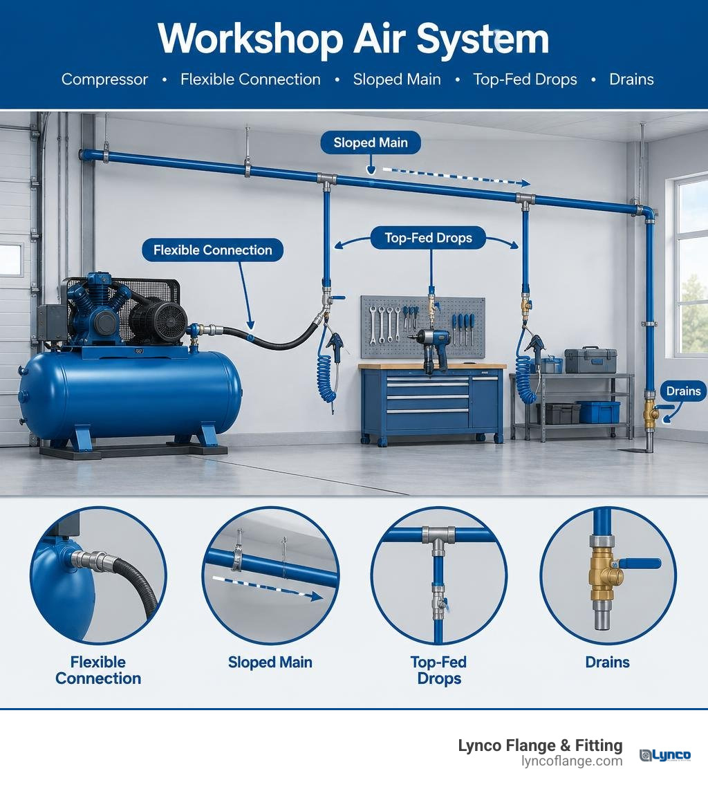
Air compressor plumbing terms to know:
Selecting the Right Materials for Air Compressor Plumbing
Every reliable workshop begins with choosing the right piping material. Compressed air systems operate under intense dynamic loads, carrying pulsing pressure waves, moisture, and aerosolized compressor oils. Picking an improper material leads to premature joint failure, severe pressure drops, or catastrophic safety risks.
Before purchasing materials, reviewing a practical guide to piping system basics helps clarify how pipe schedules, wall thicknesses, and pressure ratings operate under load. For compressed air distribution, shop owners typically choose between four core materials:
- Black Iron (Schedule 40 Steel): The traditional standard for commercial workshops. It offers immense mechanical strength and high pressure ratings exceeding 150 to 300 psi depending on fittings. However, black iron is heavy, labor-intensive to thread and hang, and naturally susceptible to internal corrosion when exposed to moisture.
- Copper (Type L or Type K): A favorite among home craftsmen and auto body shops. Copper delivers a completely corrosion-free internal surface that keeps downstream air pristine. Soldering joints takes practice, and material costs fluctuate, but Type L copper easily handles 150 to 200+ psi working pressures at workshop temperatures.
- Modular Aluminum Piping: Modern, engineered aluminum air systems feature silky-smooth internal bores that minimize friction loss. They utilize push-fit or compression fittings with nitrile O-rings, cutting installation labor in half. Aluminum never rusts, weighs about 40% less than steel, and is rated up to 190 psi across typical operating temperatures (0°F to 140°F).
- PEX (Cross-Linked Polyethylene): PEX-a and PEX-b are tempting due to low cost and flexible routing, but standard plumbing PEX has clear limitations under air pressure. While rated around 160 psi at 73°F, its working pressure rating drops to roughly 130 psi at 120°F. If used, it must be guarded against high compressor-discharge heat, oil degradation, and direct UV light.
| Piping Material | Max Pressure Rating (at 70°F) | Relative Material Cost | Installation Difficulty | Corrosion Resistance |
|---|---|---|---|---|
| Black Iron (Sched. 40) | 150–300+ PSI | Moderate | High (cutting/threading) | Poor (prone to internal rust) |
| Copper (Type L) | 200–250+ PSI | High | Moderate (sweat soldering) | Excellent |
| Modular Aluminum | 190 PSI | Moderate–High | Low (push-to-connect) | Outstanding |
| PEX Tubing | ~160 PSI (drops at heat) | Low | Low (crimp rings) | Excellent (oil-sensitive) |
The Severe Hazards of PVC and CPVC Plastic Lines
Using standard PVC (polyvinyl chloride) or CPVC (chlorinated polyvinyl chloride) for compressed air is dangerous. While PVC is inexpensive and simple to glue for irrigation or drainage, it is fundamentally unsafe for compressed gases.
Air is a compressible gas, meaning it stores massive amounts of mechanical energy under pressure. When standard PVC pipe fails under gas pressure, it does not split with a small leak like it does with water. Instead, the brittle plastic shatters explosively, sending razor-sharp shrapnel across the workshop at dangerous velocities. Heat from the compressor pump and synthetic compressor oils accelerate this embrittlement over time.
Major safety bodies such as OSHA and plastic pipe manufacturers explicitly prohibit the use of unshielded PVC and CPVC for above-ground compressed air distribution.
Metallic vs. Modular Piping Systems
When weighing traditional metal against modern modular systems, installation labor is often the deciding factor. Threaded black iron requires pipe dies, pipe wrenches, cutting oil, and patience. Many DIY installers find that in 1/2″ black iron air compressor piping setups, using substandard fittings or relying solely on a single wrap of PTFE tape can lead to persistent micro-leaks under 100+ psi pressure.
Soldered copper and push-fit aluminum offer superior internal smoothness. A smooth bore reduces turbulence, preserves flow velocity, and eliminates internal rust flakes that can clog delicate spray guns or pneumatic nailers. Aluminum systems also allow quick reconfigurations whenever you expand your tool bench or add machinery.
Designing an Optimized Piping Layout and Sizing Strategy
A poorly planned layout chokes high-demand pneumatic tools regardless of your compressor’s horsepower. When mapping your air distribution lines, you must decide between a straight dead-end header and a closed-loop ring.
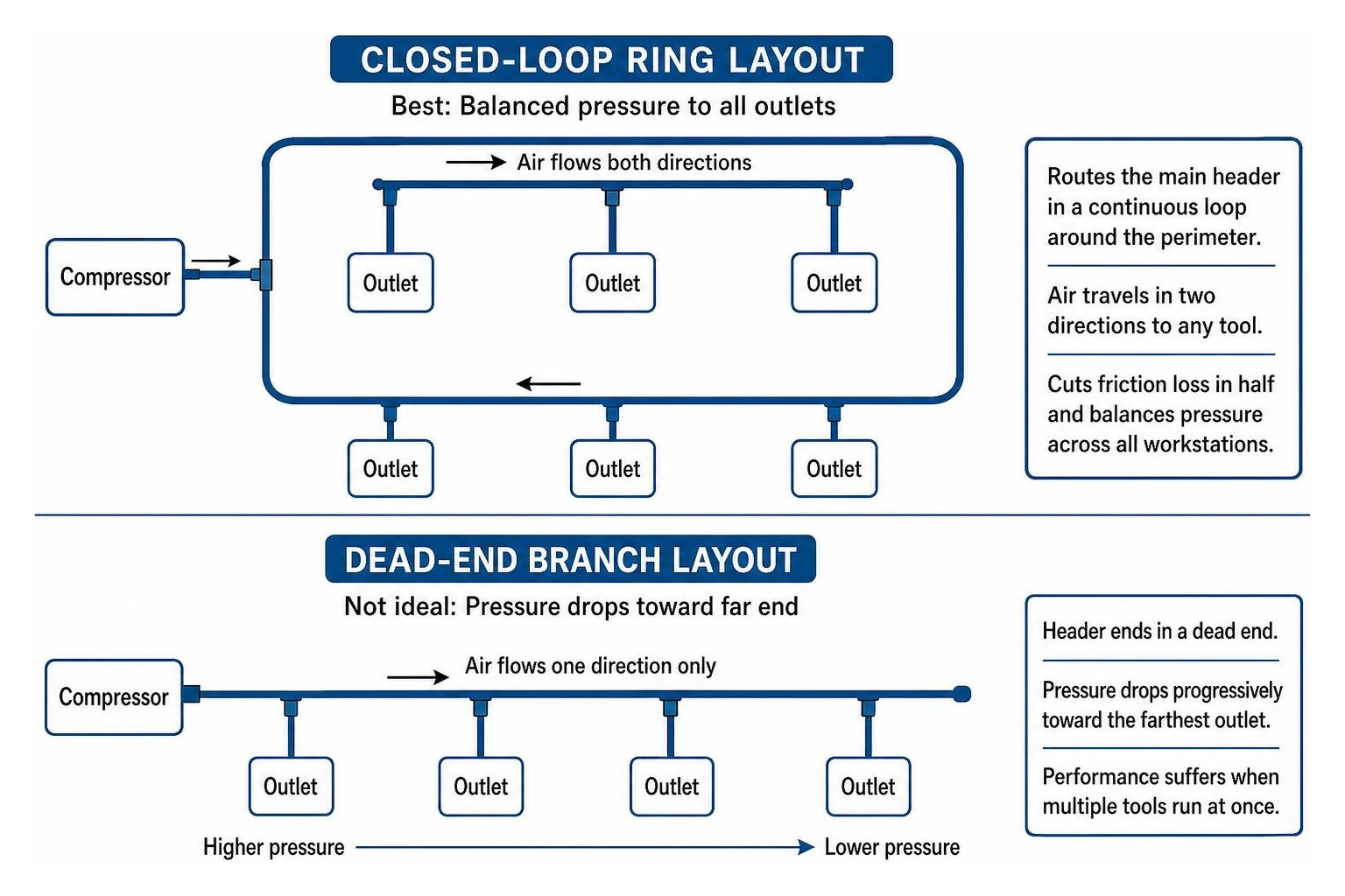
A closed-loop ring layout routes the main header in a continuous loop around the perimeter of the shop before returning to the compressor. This design allows air to travel in two directions simultaneously toward any active tool, effectively cutting friction loss in half and balancing pressure across all workstations. In contrast, a dead-end branch drops pressure progressively toward the farthest outlet whenever multiple tools run at once.
Understanding what factors should I consider when selecting pipe fittings ensures that flow-restricting 90-degree elbows, tees, and reducers do not undo the benefits of your layout.
Sizing Pipe Diameters for Tool Performance
Piping internal diameter dictates friction loss. If you push 15 to 20 CFM (cubic feet per minute) through an undersized 1/2-inch line over a 100-foot run, friction robs your tool of dynamic pressure, causing grinders to stall and impact wrenches to lose torque.
To maintain steady tool power, apply these general sizing guidelines:
- Small Garages & Single Users (Under 3 HP, < 10 CFM): 1/2-inch inside diameter pipe works well for short runs under 50 feet.
- Pro Workshops (5 to 7.5 HP, 15–25 CFM): Use a minimum of 3/4-inch pipe for the main distribution loop to minimize pressure drop over runs up to 150–200 feet. Drop lines to individual benches can step down to 1/2-inch.
- Commercial & Multi-Bay Shops (10+ HP, > 30 CFM): Run a 1-inch or larger main header to stabilize air velocity and provide storage volume within the piping network itself.
Reviewing the importance of properly sized fittings for piping systems will help you match connector bores with your distribution pipe, avoiding sudden bottlenecks at every wall drop.
Layout Geometry, Main Line Slopes, and Drop Placements
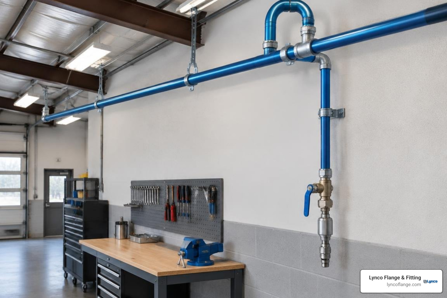
Gravity is your strongest ally when managing system moisture. Never mount your main header perfectly level. Instead, pitch the main distribution line downward away from the air compressor at a minimum slope of 1 inch for every 10 feet of horizontal run. This slope encourages condensed water to flow downstream into a dedicated low-point drain leg rather than pooling near active tool drops.
When creating drops down to workbenches:
- Take Off From the Top: Always run your branch line upward out of the top of the main header using a 180-degree “gooseneck” bend (or inverted tee) before dropping down the wall. This prevents liquid water skimming along the bottom of the main pipe from falling into your air hose.
- Extend Past the Tool Outlet: Extend the drop pipe 6 to 12 inches below the tool’s quick-disconnect regulator outlet to form a drip leg (moisture trap).
- Terminate with a Drain: Cap the bottom of the drip leg with a manual or automatic drain valve to blow out collected water periodically.
Moisture Control, Aftercoolers, and Condensate Drainage
Compressing air squeezes atmospheric water vapor into liquid droplets. Hot discharge air holds moisture as vapor; as that air cools inside your distribution lines, water condenses and coats the pipe walls. Understanding how water impacts piping over time explains why corrosion and water scale quickly shorten the lifespan of bare steel pipes and sensitive pneumatic components.
To keep lines bone-dry, implement a tiered filtration and cooling strategy:
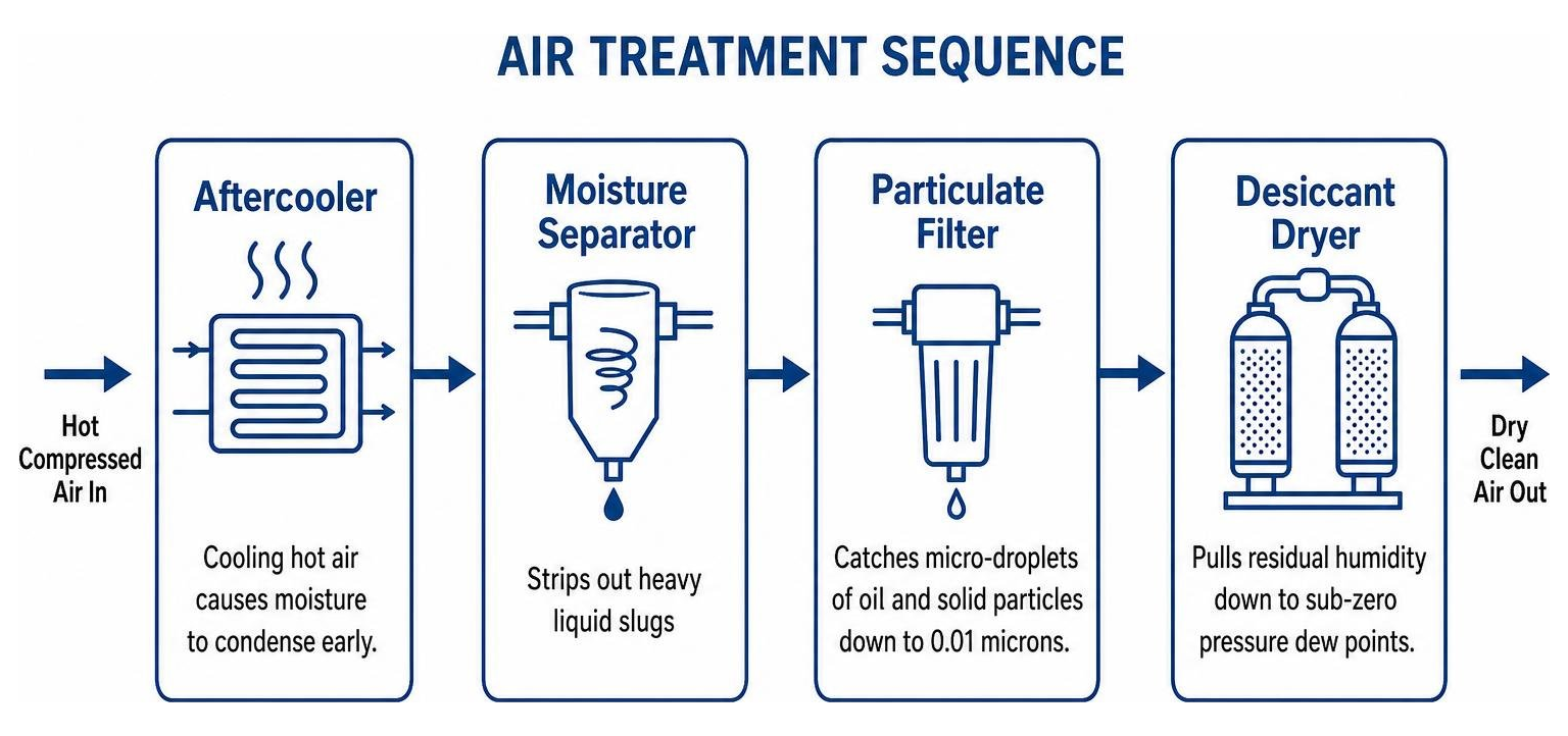
- Pre-Tank Heat Exchangers / Aftercoolers: Cooling hot air between the compressor pump and the receiver tank causes moisture to condense early, allowing it to be drained directly from the tank rather than traveling down the shop lines.
- Bulk Moisture Separators: Placed immediately downstream of the receiver tank, these spin the air centrifugally to strip out heavy liquid slugs.
- Particulate & Coalescing Filters: Installed at individual workstations to catch micro-droplets of oil and solid particles down to 0.01 microns.
- Desiccant Air Dryers: Essential for paint booths and plasma cutters, these chemical dryers pull residual humidity down to sub-zero pressure dew points.
Managing Tank and Line Drainage Effectively
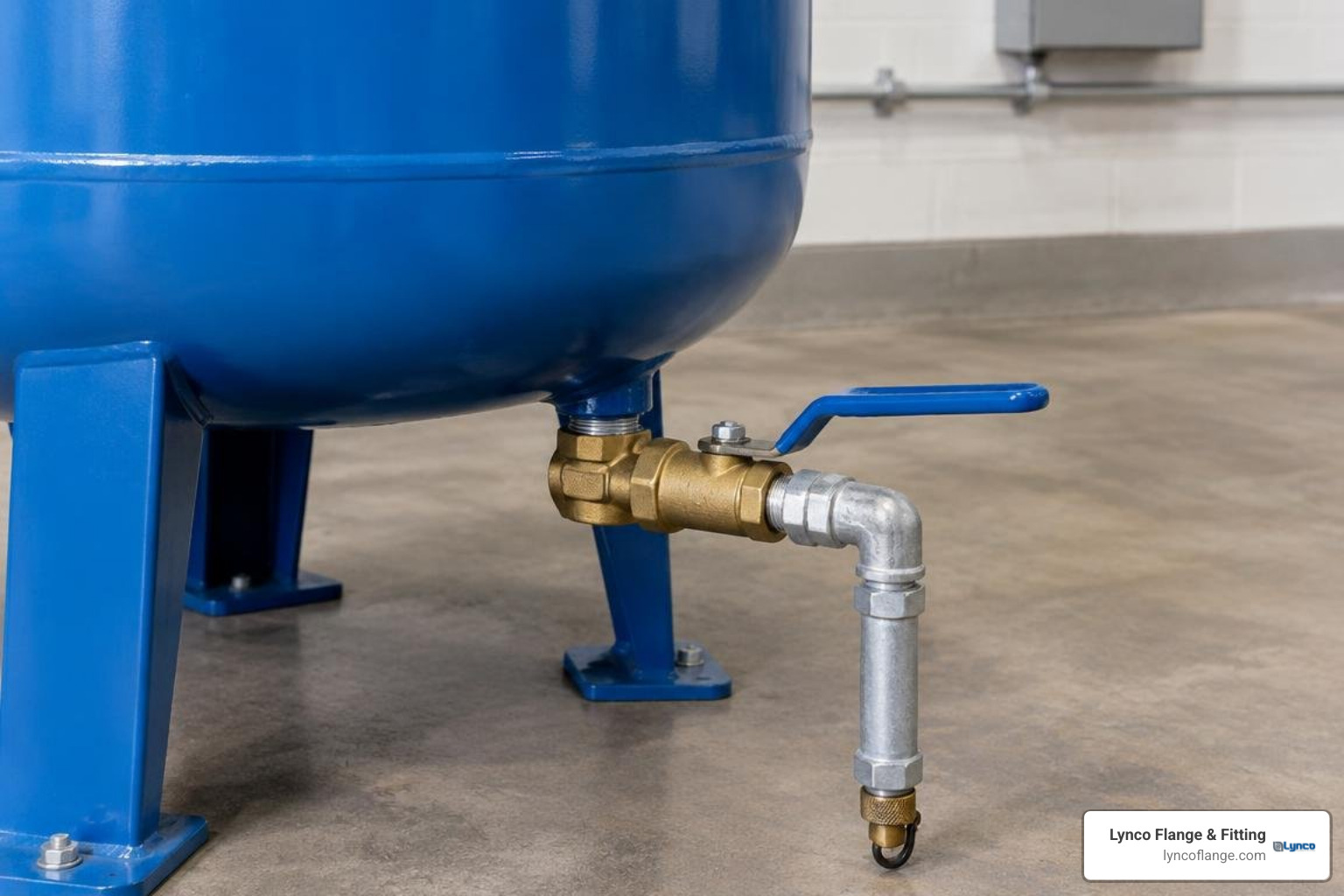
Water that pools inside your compressor tank causes internal rust and reduces the vessel’s usable air volume. Unfortunately, standard factory drain valves are often tiny petcocks tucked under the curved belly of the tank that are difficult to reach.
Many shop owners upgrade their tanks with an extended ball valve drain setup. By installing a 1/4-inch or 3/8-inch solid brass street elbow, a short nipple, and a quality full-port ball valve routed to the front or side of the compressor base, draining the tank becomes a quick, clean daily task. For automated operation, install an electronic timed solenoid valve that vents condensate for 3 seconds every 45 minutes of run time.
Compressor Setup, Vibration Isolation, and Electrical Planning
Where and how you mount your compressor directly affects maintenance access, noise levels, and plumbing integrity. While placing a noisy unit in a separate outdoor enclosure or shed protects shop quiet, ensure the space has adequate ventilation louvering and freeze protection. Air compressor pumps generate significant thermal energy; running a pump in a sealed, unventilated closet can trigger thermal overloads or cause motor failure.
On mobile rigs, service trucks, or dual-voltage shop setups, always match power demands to appropriate wire sizes. The Wiring Diagram – Viair Corp demonstrates how high-current direct-current systems suffer steep voltage drops when wire gauge is undersized over long runs (for example, a 12V circuit drawing 20 amps requires 14 AWG at 5 feet, but steps up to 8 AWG over a 20-foot run).
Isolating Vibration and Thermal Expansion
Never hard-pipe rigid black iron, copper, or aluminum directly to your compressor tank’s discharge port. Reciprocating pistons generate constant harmonic vibration that will fatigue rigid pipe joints, leading to cracked fittings or broken tank bungs.
Instead, isolate the system using these best practices:
- Flexible Jumper Hose: Connect the tank discharge port to the wall-mounted rigid header using a high-pressure, wire-braided hydraulic hose, stainless-steel flex connector, or high-grade flexible whip line rated for at least 200–250 psi.
- Rubber Vibration Pads: Anchor the compressor feet to the concrete floor using heavy-duty elastomeric or neoprene isolation pads. Tighten anchor nuts just enough to compress the rubber without crushing it solid.
- Expansion Loops & Clip Spacing: Aluminum and copper expand and contract with temperature shifts. Support horizontal lines with dedicated wall clips placed every 6 to 10 feet (32 inches for PEX), keeping clamps at least 6 inches away from corner fittings to allow natural expansion.
Step-by-Step Installation, Sealing, and Pressure Testing
Taking a methodical approach to cutting, mounting, and sealing your air lines prevents frustrating air leaks once the system is pressurized.
Before picking up tools, review these practical safety tips for industrial piping installation. Following proven protocols for installing a piping system ensures structural security from the first bracket to the final drop.
Selecting Fittings and Regulators for Air Compressor Plumbing
NPT (National Pipe Thread) is the North American standard for pneumatic fittings. Because NPT threads are tapered, they create a mechanical seal as the male and female wedges draw together.
To ensure leak-tight connections:
- Thread Sealant Combination: Wrap male NPT threads with 2 to 3 turns of high-density PTFE tape (wrapped clockwise), then top with a thin, smooth layer of anaerobic PTFE pipe dope. This dual-layer approach lubricates the threads to prevent galling and fills microscopic voids.
- Quick-Connect Couplers: Use solid brass industrial interchanges, such as T TANYA HARDWARE Air Hose Fittings & Coupler Female Plug, 1/4-Inch NPT. Solid brass resists wear and corrosion much better than soft aluminum. Be consistent with your plug style: Industrial (Type D/I/M) is the most common standard, whereas Automotive (Type C/T) uses a slightly longer nose profile that will not seal in an industrial coupler.
- Point-of-Use FRL Units: Install a Filter-Regulator-Lubricator (FRL) module at each drop where air tools run continuously. If you plan to spray paint or run clean plasma cutting lines, omit the in-line lubricator and dedicate that drop to clean, dry air.
Assembly, Joint Sealing, and Soapy Water Leak Checks
Once all pipe clips and fittings are secured, commission the system carefully:
- Deburr Every Cut: Use an internal/external reaming tool to remove all burrs and metal chips from pipe ends. Stray shavings can ruin regulator seals and internal tool vanes.
- Gradual Pressurization: Close all drop ball valves. Power up the compressor and slowly pressurize the network to 50 psi. Listen for obvious hissing or fitting movement.
- Soapy Water Bubble Test: Spray every joint, union, threaded nipple, and valve with a solution of liquid dish soap and warm water (or commercial leak detection fluid). Watch for expanding froth or growing bubbles, which indicate micro-leaks.
- Full Working Pressure Test: If the 50 psi check passes, raise the pressure to your standard cut-out level (typically 125 to 150 psi). Re-check all fittings with soapy water.
- Hold Test: Shut off the compressor and record the tank gauge reading. Leave the pressurized system undisturbed overnight. If the system loses more than 2 to 3 psi over an eight-hour period, trace down your remaining valve or coupler leaks.
Routine Maintenance and Troubleshooting for Air Compressor Plumbing
A well-installed distribution system requires minimal upkeep, but regular maintenance preserves efficiency:
- Daily / After-Shift Drainage: Crack open drip-leg valves and tank drains to vent accumulated water. If you run in humid environments, install automatic drains to eliminate manual chores.
- Monthly Intake Filter Inspection: Clean or replace the compressor pump’s air intake filters every 2 to 3 months. A clogged intake starves the pump, extending cycle times and increasing heat buildup.
- Quarterly Leak Audits: Walk your piping runs with soapy spray or an ultrasonic acoustic leak detector. Even tiny 1/16-inch leaks running continuously at 100 psi waste thousands of kilowatt-hours of electrical power each year.
- Regulator & Filter Element Changes: Replace point-of-use particulate and coalescing filter elements once their differential pressure gauge enters the red zone, or annually during routine shop maintenance.
Frequently Asked Questions About Compressed Air Piping
Can PEX tubing be safely used for air compressor lines?
Standard plumbing PEX can handle compressed air only under strict limitations. While rated for roughly 160 psi at room temperature, its burst rating drops quickly above 100°F—temperatures easily reached right off a compressor pump head. PEX is also degraded by direct sunlight (UV) and certain synthetic compressor oils. If you use PEX, connect at least 6 to 10 feet of metallic pipe off the compressor discharge to cool the air first, shield the tubing from UV exposure, and ensure your system pressure regulator never exceeds 120 psi.
What pipe size should I use for a 5 to 7.5 HP compressor?
For a 5 to 7.5 HP shop compressor producing 15 to 25 CFM, use a 3/4-inch inside diameter pipe for your main header or distribution loop. A 1/2-inch main line creates excessive friction loss over long runs, causing noticeable pressure drops during continuous tool use (like sandblasting or dual-action sanding). Drop legs feeding individual hose reels or benches can safely step down to 1/2-inch pipe.
Why must branch drops always come off the top of the main line?
Taking branch lines off the top of the main line via a gooseneck bend prevents water contamination. As compressed air cools, liquid condensate clings to the bottom and sides of the pipe, flowing downward with gravity. If you take a drop from the bottom of the main line, it acts as a funnel, dumping accumulated liquid water and scale directly into your air hose and air tools. Top takeoffs pull clean, dry air from the center of the pipe while letting moisture travel harmlessly down to dedicated low-point drains.
Conclusion
Plumbing an efficient, safe compressed air network transforms your workshop from a cluttered web of tangled floor hoses into a professional, productive workspace. By avoiding dangerous materials like PVC, sizing your main loop with at least 3/4-inch diameter pipe, pitching lines toward low-point moisture drains, and isolating compressor vibration, you guarantee steady pressure and dry air for every tool in your lineup.
When designing or upgrading industrial distribution systems, selecting premium, code-compliant components is essential. Explore what an industrial piping system is made of to see how Lynco Flange & Fitting delivers engineering-backed flange and fitting solutions tailored for demanding pressure applications across North America.