Discharge Line and Suction Line: What’s the Difference?
The discharge line and suction line carry refrigerant vapor on opposite sides of the compressor. The discharge line sends hot, high-pressure vapor from the compressor to the condenser. The suction line returns cooler, low-pressure vapor from the evaporator to the compressor. The suction line is usually larger and insulated; the discharge line is hot and typically left uninsulated. Neither is the liquid line, which carries refrigerant away from the condenser.
I’m Lance Vanover, and I’ve spent more than 26 years in industrial flange and pipe fitting operations, where line identification and pressure requirements shape fitting decisions. I’ll use that piping perspective to explain the discharge line and suction line, starting with the differences a tech needs to recognize.
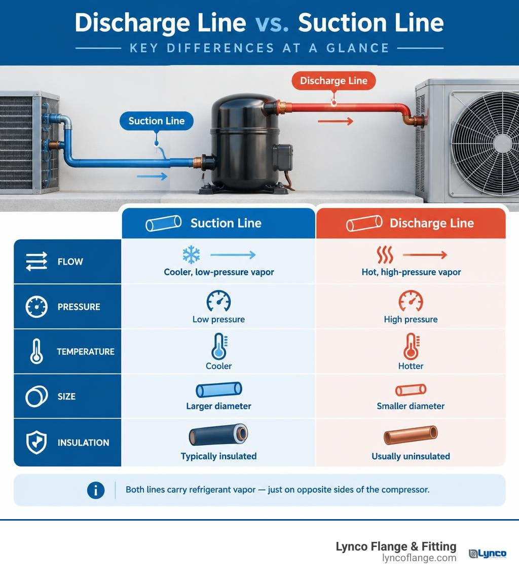
Discharge line and suction line definitions:
Core Differences Between the Discharge Line and Suction Line
Understanding the mechanical dynamics of any closed-loop cooling or process loop requires grasping a practical guide to piping system basics. At the center of vapor-compression thermodynamics sit the discharge and suction lines. These lines form the critical bridge between the heart of the system—the compressor—and the heat exchangers that manage thermal energy.
To understand their core behaviors, explore this breakdown of basic refrigerant circuit principles. The suction line operates as the intake, pulling expanded, cold vapor into the compressor cylinder or scroll set. The discharge line functions as the high-energy exhaust, pushing superheated, pressurized vapor toward the condenser coil.
| Parameter | Suction Line | Discharge Line (Hot Gas Line) | Liquid Line (For Comparison) |
|---|---|---|---|
| Location | Evaporator outlet to compressor inlet | Compressor outlet to condenser inlet | Condenser outlet to expansion device |
| Refrigerant State | Low-pressure, superheated vapor | High-pressure, superheated vapor | High-pressure, subcooled liquid |
| Typical Operating Pressure (R-410A) | ~120 psi (8.3 bar) | ~380 to 450 psi (26.2 to 31.0 bar) | ~380 to 450 psi (26.2 to 31.0 bar) |
| Typical Operating Pressure (R-22) | ~70 psi (4.8 bar) | ~230 to 260 psi (15.9 to 17.9 bar) | ~230 to 260 psi (15.9 to 17.9 bar) |
| Typical Operating Temperature | 40°F to 55°F (4.4°C to 12.8°C) | 140°F to 200°F+ (60°C to 93.3°C+) | 85°F to 105°F (29.4°C to 40.6°C) |
| Nominal Line Sizing (OD) | Larger (3/4″ to 1-1/8″+) | Moderate (1/2″ to 7/8″+) | Small (1/4″ to 3/8″+) |
| Standard Insulation Requirement | Mandatory (closed-cell foam) | Rare (safety/ambient exposure only) | Optional (extreme ambient only) |
Primary Roles in the Refrigeration Cycle
The compressor divides a cooling circuit into two distinct pressure regimes: the high side and the low side.

- The Suction Line (Low-Pressure Vapor Return): The suction line runs from the evaporator outlet directly to the compressor inlet suction port. Its primary purpose is to deliver low-temperature, low-pressure gas while guaranteeing that every ounce of liquid refrigerant has boiled away into vapor. If liquid drops enter the suction port, non-compressible fluid will cause hydraulic shock—often breaking valves, bending connecting rods, or shattering scroll plates.
- The Discharge Line (High-Pressure Hot Gas Delivery): The discharge line—often termed the hot gas line—starts at the compressor discharge valve and terminates at the condenser inlet header. Its mission is to carry high-pressure superheated vapor into the condenser, where ambient air or water strips away sensible and latent heat, condensing the vapor into a subcooled liquid.
Physical Sizing Differences for the Discharge Line and Suction Line
A common question from apprentice technicians is: Why is the cold suction pipe significantly larger than the hot discharge pipe? Both lines transport roughly the same mass flow rate of refrigerant per minute, but the volumetric flow rate is radically different.
This difference comes down to vapor density. At lower suction pressures (such as 120 psi for R-410A or 70 psi for legacy R-22), vapor expands, taking up far more physical volume per pound of refrigerant. At discharge pressures (380 psi or higher), the compressor compresses that vapor into a tight, dense, high-pressure stream.
To keep internal friction low without strangling compressor efficiency, we must master pipeline flow and pressure importance. Piping designers limit line friction so total saturation pressure loss does not exceed 2 to 3°F (1.1 to 1.7°C) of equivalent temperature drop across the run.
- Sizing a suction line too small creates excessive friction and pressure drop, starving the compressor, spiking compression ratios, and drastically slashing tonnage capacity.
- Sizing a suction line too large drops flow velocity below the point where refrigerant gas can drag compressor oil back up vertical lines, risking lubrication starvation.
Thermal Dynamics, Insulation, and Oil Management
Temperature control and fluid dynamics separate commercial piping from basic plumbing. When dealing with specialized lines, understanding the science of a piping system allows engineers to anticipate how thermal expansion, heat transfer, and fluid shear behave under load.
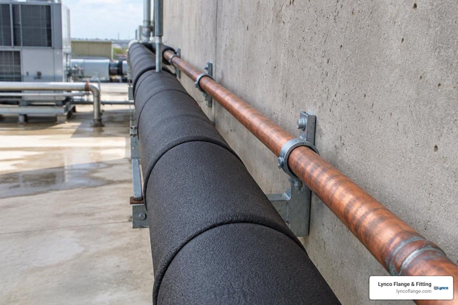
Insulation Requirements: Suction Line vs. Discharge Line
Should both lines be insulated? In 95% of standard installations, the answer is no.
The Suction Line Demands Heavy Closed-Cell Insulation: Because the suction line runs at temperatures lower than the surrounding ambient dew point (typically 40°F to 50°F), exposed copper will sweat profusely. Left bare, water drips onto building materials, leading to mold, structural rotting, and corrosion.
Uninsulated suction lines absorb heat from attics, mechanical rooms, or outdoor air. This sensible heat gain superheats the vapor before it hits the compressor, driving up internal discharge temperatures and decreasing overall system operating efficiency by up to 10%.
The Discharge Line Stays Bare (With Important Exceptions): The discharge line runs hot—often reaching 150°F to 200°F (65°C to 93°C). Because it is hotter than ambient air, it sheds heat naturally. This preliminary sensible heat rejection is helpful because it eases the thermal workload on the condenser.
Insulation is applied to discharge lines only in specific cases:
- Personnel Safety: When routed through walkways or low-clearance service corridors where maintenance crews could suffer severe thermal burns.
- Extreme Ambients: When routed outdoors through freezing climates where sudden winter drafts could cause premature hot gas condensation inside vertical risers during sub-zero operation.
- Acoustic Dampening: In commercial spaces where compressor discharge pulsation creates objectionable noise throughout adjacent occupied walls.
Managing Oil Return in the Discharge Line and Suction Line
Compressors circulate a specific ratio of lubricating oil (mineral, alkylbenzene, or polyolester/POE) along with the refrigerant vapor. Unlike water and steam, oil travels through the system by mechanical entrainment—literally swept along by the velocity and shear force of the passing gas.
To guarantee that oil does not settle in low pockets or coat interior coil surfaces, consult the engineering practices detailed in the Refrigerant Piping Design Guide.
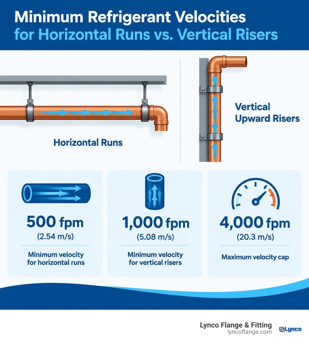
Industry standards require:
- Horizontal Runs: Maintain a minimum refrigerant gas velocity of 500 feet per minute (fpm) (2.54 m/s).
- Vertical Upward Risers: Maintain a minimum refrigerant gas velocity of 1,000 fpm (5.08 m/s) to lift entrained oil droplets upward against gravity.
- Maximum Velocity Cap: Keep overall velocity below 4,000 fpm (20.3 m/s) to prevent erosion, line chatter, and high pressure drops.
When designing variable-capacity systems or multi-stage chillers where capacity drops during part-load operations, designers install double suction risers. A double-riser setup splits the line into two parallel vertical pipes with a trap at the base; when flow drops, the trap fills with oil, sealing off the larger pipe and forcing high-velocity gas through the smaller pipe to maintain oil lift.
Troubleshooting and Best Practices for Line Sizing and Installation
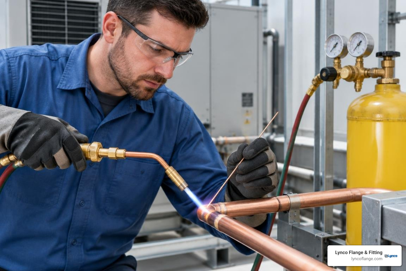
Field reliability depends on quality fabrication, proper materials, and understanding what piping systems are constructed of. Air conditioning and refrigeration (ACR) systems rely on clean, dehydrated, seamless Type L or Type K copper lines, brazed using high-silver or phosphorus-copper filler alloys.
Common Faults: Leaks, Blockages, and Pressure Drops
Refrigerant lines operate under demanding thermal and mechanical stress:
- Vibration Fatigue and Leaks: Discharge lines experience pulsation waves straight off the compressor discharge stroke. Without vibration absorbers or wide-radius sweeping bends, work-hardening occurs at fittings, creating stress fractures. A leak on a discharge line releases oil and refrigerant rapidly due to high operating pressures (over 350 psi on modern R-410A units).
- Suction Line Restrictions: Dented suction tubing, plugged suction-line filter-driers, or kinked elbows create immediate pressure drops. A 3 psi extra drop across a suction line drops cooling capacity by roughly 2.5% and spikes compressor power consumption.
- Oil Logging: If horizontal lines lack pitch or if vertical risers are oversized, oil drops out of the vapor stream and puddles in low spots. This starves the compressor crankcase, leading to mechanical bearing seizure, while filling the evaporator and cutting heat transfer efficiency.
Installation Rules: Traps, Slopes, and High-Pressure Safety
Installing refrigeration lines correctly requires following essential field practices detailed in pipelines basics explained:
- Slope Requirements: Pitch all horizontal suction and discharge lines downward in the direction of refrigerant flow at a minimum slope of 1/4 inch per 10 feet (or 1/8 inch per foot in tight commercial runs). This lets gravity pull oil along the pipe floor.
- Inverted Traps on Discharge Runs: When the condenser sits elevated above the compressor, install an inverted trap that rises above the top condenser coil before turning downward into the inlet. This prevents condensed liquid refrigerant and entrained oil from draining back into the compressor discharge head during off-cycles.
- Dry Nitrogen Purging: When brazing copper lines, continuously sweep dry nitrogen at 3 to 5 SCFH through the tubing. Without nitrogen, internal oxygen reacts with hot copper, creating black cupric oxide scale that flakes off and plugs expansion valves, filter driers, and oil screens.
- High-Pressure Safety Precautions: Always remember that discharge lines operate under dangerous pressure and high temperature. Never open or cut a discharge line without verifying zero pressure via calibrated manifold gauges. Use personal protective equipment, including heat-resistant gloves and safety glasses, to avoid flash burns from escaping hot vapor.
Frequently Asked Questions About Compressor Refrigerant Lines
How do operating pressures differ between R-22 and R-410A lines?
R-410A operates at pressures roughly 50% to 60% higher than legacy R-22 systems.
Under normal cooling conditions:
- R-22: Operates at a suction pressure of approximately 68 to 75 psi (evaporating around 40°F) and a discharge pressure of 210 to 250 psi.
- R-410A: Operates at a suction pressure of approximately 118 to 130 psi (evaporating around 40°F to 44°F) and a discharge pressure between 375 and 450 psi.
Because of these elevated pressures, R-410A systems require heavier wall thickness (ACR Type L copper minimum) and fittings engineered to withstand high burst pressures.
Does a discharge line ever require insulation?
Under standard residential and light commercial conditions, discharge lines should be left uninsulated to promote ambient heat dissipation before the condenser. However, insulation is necessary when the hot gas line runs through unconditioned spaces where freezing temperatures could cause premature condensation, through accessible hallways where it poses a burn risk to building occupants, or where sound dampening is required.
What happens to the system if the suction line is oversized?
While a larger suction line reduces friction and pressure drop, oversizing it drops the refrigerant vapor velocity below the critical threshold (500 fpm horizontal, 1,000 fpm vertical). When velocity falls, refrigerant gas can no longer drag entrained lubricating oil upward back to the compressor. The oil stays trapped in the evaporator, leading to loss of cooling capacity and catastrophic compressor bearing failure due to oil starvation.
Conclusion
Understanding how the discharge line and suction line differ keeps cooling equipment running efficiently and prevents expensive compressor breakdowns. Sizing these lines correctly balances pressure drops against minimum oil-return velocities. Insulating the low-pressure suction line prevents condensation, while keeping the high-pressure discharge line secure protects technicians from high operating temperatures and pressures.
Whether you are designing large industrial HVAC runs or commercial process piping, reliable operations start with precision components. To learn more about pipe ratings and heavy-duty materials, review our guide to what industrial piping systems are made of. For high-pressure connections and custom fittings that meet exact field tolerances, reach out to our team at Lynco Flange & Fitting for reliable guidance and fast turnaround.