What Is a Piping System?
A piping system is a connected network that moves liquids, gases, or slurries between equipment or through a building. It includes pipe, fittings, valves, and joints, along with supports and other parts needed to control flow and keep the system secure.
For industrial projects, those parts must work together under the system’s pressure, temperature, and service conditions. A fitting or flange that does not match the design can create a leak risk or delay installation. This guide covers the basics of how piping systems are built, selected, and kept reliable.
I’m Lance Vanover, CEO of Lynco Flange & Fitting. I’ve spent more than 26 years in industrial flange and fitting operations, helping teams source components for a piping system.

Core Components and Mechanics of a Piping System
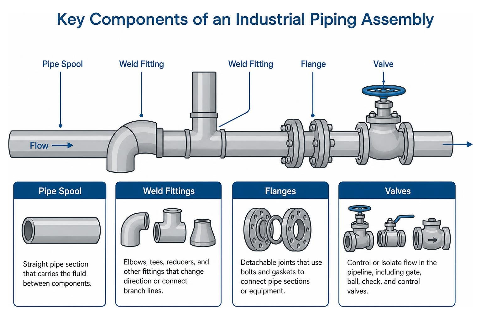
To understand how these networks handle intense pressure, thermal shifts, and hazardous fluids, we must examine the mechanics of a piping system. Every component performs a distinct mechanical role to maintain continuous containment and smooth flow.
- Straight Pipe Spools: The primary conduits conveying the fluid medium over distance. These are sized by Nominal Pipe Size (NPS) and schedule (wall thickness) to resist internal burst pressures.
- Weld Fittings: Elbows (45° and 90°), tees, crosses, and reducers (concentric and eccentric). Knowing how to choose the right weld fittings ensures directional changes or line reductions do not cause excessive turbulence, erosion, or sudden pressure drops.
- Isolation and Control Valves: Gate and ball valves provide complete on/off isolation, globe valves offer precise throttling, check valves prevent reverse flow, and control valves automatically balance operational throughput.
- Flanges and Gaskets: Recognizing the importance of flanges in industrial piping systems is essential for field maintenance. Flanges (such as weld neck, slip-on, socket weld, or blind) provide detachable mechanical joints, clamping compressible gaskets (spiral-wound, ring type joint, or sheet) to form a leak-tight seal.
- Structural Supports and Hangers: Rigid struts, variable spring hangers, guides, and anchors that transfer deadweight (pipe, fluid, and insulation), thermal expansion forces, and dynamic seismic loads directly to structural steel.
- Thermal Expansion Joints and Loops: Engineered metallic bellows, flexible hoses, or expansion loops that absorb dimensional changes caused by thermal cycling, protecting sensitive equipment nozzles from bending moments.
Major Types and Classifications of Piping Across Industries
Piping assemblies are classified by their operational environment, design criteria, fluid toxicity, and structural boundary limits.
Industrial Process and Utility Configurations
Industrial plants rely on specialized piping arrangements to handle challenging physical and chemical processes:
- Process Piping: Found inside refineries and chemical processing facilities to transport raw hydrocarbons, intermediate reactants, and aggressive chemicals under varying pressures and temperatures.
- Utility Piping: Feeds auxiliary services, including cooling water, inert nitrogen purging, and high-pressure steam distribution.
- Jacketed Lines: Feature an outer pipe wrapped around an inner process line. Heating mediums (such as steam or thermal oil) circulate within the annular space to keep viscous fluids like asphalt or sulfur molten.
- Cryogenic Transfer: Engineered for temperatures reaching as low as -196°C (-321°F) for liquefied gases (LNG, liquid nitrogen). These systems demand specialized alloys that resist low-temperature embrittlement.
- Compressed Air Distribution: Facilities rely on dedicated piping systems for compressed air distribution/05%3ACompressorsAftercoolersPipingSystems/5.03%3APipingSystemsforCompressedAirDistribution), where using continuous loops rather than dead-end grid runs maintains balanced pressure and prevents air starvation at remote stations. A single 1/2-inch air leak can waste roughly 12 million cubic feet of air every month, costing upward of $1,200 in unnecessary compressor power.
- Slurry Transport: Heavy-wall, abrasion-resistant piping designed to move abrasive solid-liquid mixtures across mining, mineral processing, and dredging operations.
Commercial HVAC and Plumbing Infrastructure
In commercial and institutional buildings, piping delivers comfort, potable water, and life-safety utilities:
- Hydronic Heating and Cooling: A commercial integrated piping system integrates chilled water and hot water distribution directly with fan coil equipment, circulating conditioned fluid across multistory complexes.
- Domestic Potable Water: Copper, stainless steel, and cross-linked polyethylene (PEX) networks delivering hot and cold drinking water under regulated municipal pressures.
- Sanitary and Storm Drainage: Unpressurized gravity systems sloped precisely (often 1/8 to 1/4 inch per foot) to transport wastewater, venting sewer gases through roof stacks.
- Fire Suppression Systems: Wet, dry, or deluge sprinkler pipe networks built to strict NFPA standards to ensure immediate flow during fire emergencies.
Piping Systems vs. Cross-Country Pipelines
While both transport fluids, piping systems and cross-country pipelines operate under different engineering, geographical, and regulatory constraints.
| Feature / Parameter | Plant Piping System | Cross-Country Pipeline |
|---|---|---|
| Geographic Scope | Confined within plant or facility battery limits | Spans hundreds or thousands of miles across diverse terrain |
| Component Density | High concentration of fittings, valves, flanges, and instruments | Primarily long runs of straight line pipe with minimal valving |
| Governing Codes | ASME B31.3 (Process), ASME B31.1 (Power), ASME Section III | ASME B31.4 (Liquid Hydrocarbons), ASME B31.8 (Gas Transmission) |
| Loading Conditions | Dominated by thermal expansion, structural anchor motion, and nozzle loads | Dominated by internal hoop stress, soil settlement, and surge transients |
| Support Structure | Suspended from structural racks, concrete sleepers, and hangers | Buried underground, laid on the seabed, or placed on overland berms |
Material Selection and Governing Design Codes
Selecting the right alloy and following established design codes ensures a system can safely handle its design pressures and operational temperatures.
Selecting Common Piping Alloys and Non-Metallic Materials
Understanding what industrial piping systems are constructed of helps engineers balance mechanical strength, corrosion allowance, weight, and procurement budgets:
- Carbon Steel (e.g., ASTM A106 Gr. B, A53): The standard workhorse for high-strength, elevated-temperature utility and hydrocarbon service.
- Stainless Steel (e.g., ASTM A312 TP304L/316L): Offers chromium-nickel corrosion resistance, making it suitable for chemical processing, food and beverage lines, and marine environments.
- Low-Temperature and Chrome-Moly Alloys (e.g., ASTM A333 Gr. 6, ASTM A335 P11/P22/P91): Engineered for extreme conditions—A333 retains impact toughness down to -50°F (-45°C), while chrome-moly grades handle high creep temperatures in power boilers.
- Copper and Brass: Primarily selected for commercial potable water, instrument air lines, and refrigerant circuits due to corrosion resistance and thermal conductivity.
- Thermoplastics (PVC, CPVC, HDPE, PVDF): Lightweight and impervious to electrochemical corrosion, these materials excel in water treatment, acid pickling lines, and low-pressure drainage.
ASME B31 Code Compliance and Industry Standards
Engineered pressure systems must comply with North American and international consensus standards:
- ASME B31.3 (Process Piping): Governs design, materials, fabrication, assembly, and testing for chemical plants, refineries, and hydrocarbon processing facilities.
- ASME B31.1 (Power Piping): Applies to high-pressure steam and water systems in electric power generation plants and industrial institutional boilers.
- Flange and Component Dimensions: Designers depend on understanding flange standards and specifications such as ASME B16.5 (up to NPS 24) and ASME B16.47 (NPS 26 and larger) to ensure bolt circles, gasket seating surfaces, and wall transitions align properly.
- ASME Section III: The benchmark for nuclear safety-related piping, requiring full material traceability and detailed dynamic qualification.
- ASTM Specifications: Establish strict material chemistry, mechanical yield and tensile limits, and manufacturing testing requirements across all pipe and fitting products.
Engineering Design, Stress Analysis, and Modeling Software
Designing an industrial piping system requires calculating fluid velocities, sizing line diameters, placing pipe supports, and accounting for thermal movement.

Designing a Safe and Efficient Piping System
Piping design balances fluid flow efficiency with structural safety:
- Hydraulic Sizing and Velocity: Sizing lines keeps pressure drops within 5% to 10% of design thresholds, preventing cavitation in pumps and minimizing erosion along fitting walls.
- Thermal Flexibility: In high-temperature lines, applying the science of a piping system is critical. Lines running above 150°F (65°C) require thermal stress analysis to ensure expansion does not overstress equipment nozzles or exceed code-allowable stresses.
- Seismic and Dynamic Drift: Systems categorized with an Importance Factor (Ip) of 1.5 must withstand dynamic forces, maintaining relative displacement limits often within 1/100 of the story height to keep lines intact during seismic events.
- Support Span Rules: For small-bore lines (NPS 2 and smaller) and instrument tubing, engineers often apply standard span tables and prequalified support spacing instead of running detailed computer simulations for every run.
- Equipment Nozzle Boundaries: Piping stress engineers must design routing and support configurations so that thermal thrusts stay within allowable nozzle load limits specified by pump (API 610) and turbine (NEMA SM 23) manufacturers.
Digital Engineering Tools for Layout and Stress Analysis
Modern facilities are designed and reviewed in integrated digital environments:
- Stress Analysis Software (CAESAR II, AutoPIPE): Finite-element tools that calculate sustained, thermal, and occasional stress loads, verifying compliance against ASME B31 code equations.
- 3D Layout and Modeling Platforms: Applications utilize spec-driven piping modeling to place fittings and flanges according to project piping specs, preventing incompatible components from entering the bill of materials.
- Building Information Modeling (BIM): Tools for creating piping systems in BIM streamline MEP coordination, helping engineers assign fluid systems, check slope angles, and resolve interdisciplinary clashes before construction begins.
- Automated Isometric Generation: Platforms use ISOGEN engines to convert 3D coordinates into fabrication spool sheets with cut lengths, weld identification numbers, and component bills of materials.
- Verification and Validation (V&V): Safety-critical applications require software validated against benchmarks like NRC NUREG/CR-1677, ensuring calculations match field physics.
Installation Best Practices, Failure Prevention, and Maintenance
A well-engineered design still depends on quality fabrication, careful alignment, and consistent maintenance in the field.

Installation Procedures and Commissioning Verification
Field teams follow structured quality processes from spool receipt to startup:
- Fabrication and Fit-Up: Following key considerations when installing piping systems ensures pipe ends are prepped, beveled, and aligned without forcing joints into position, which can introduce residual assembly stress.
- Flange Bolting Management: Mechanics use proper flange installation methods—including cross-pattern star torque sequences, calibrated tools, and lubricated studs—to maintain even gasket seating stress and prevent flange leaks.
- Hydrostatic and Pneumatic Testing: Before service, lines are isolated and hydrostatically proof-tested (typically at 1.5 times the design pressure for ASME B31.1 or 1.5 times the internal design gage pressure adjusted for temperature per ASME B31.3) to confirm structural integrity.
- Flushing and Chemical Cleaning: Systems are purged of mill scale, weld slag, and jobsite debris using high-velocity water or chemical flushes to protect downstream valves, turbines, and instrumentation.
- As-Built Reconciliation: Field engineers verify that final pipe support locations, valve orientations, and clearances match the original stress calculations, avoiding discrepancies between the model and the actual installation.
Addressing Vibration, Water Hammer, and Corrosion Failure Modes
Unplanned plant shutdowns often stem from unmitigated mechanical dynamics or corrosion:
- Vibration Fatigue: High-frequency vibration from rotating equipment or flow-induced acoustic resonance can cause fatigue cracking at small-bore branch connections and socket welds. Adding bracing and damping supports stabilizes these vulnerable points.
- Water Hammer Mitigations: Rapid valve closures or sudden pump trips generate high-pressure shockwaves that travel through liquid columns. Installing surge relief valves, pulsation dampeners, and slow-closing actuators protects lines from hydraulic shock.
- Corrosion Management: Implementing non-destructive examination (NDE) and maintaining and inspecting weld fittings through ultrasonic thickness testing, profile radiography, and corrosion-under-insulation (CUI) programs detects wall thinning early.
- Standardized Repairs: When damage or localized thinning occurs, maintenance teams follow ASME PCC-2 standards for engineered welded split repair tees, flush patches, or non-metallic composite wraps to restore pressure containment.
Frequently Asked Questions About Piping Networks
What is the primary difference between process piping and power piping?
The distinction lies in their operating codes, facility scopes, and safety factors. Process piping falls under ASME B31.3 and applies to chemical processing facilities, hydrocarbon refineries, pharmaceutical plants, and industrial terminals handling diverse chemicals and hydrocarbons. Power piping falls under ASME B31.1 and governs steam-generation loops, boiler external piping, and feedwater cycles in electric power plants and central heating facilities. ASME B31.1 uses conservative allowable stress values to account for continuous high-temperature, high-pressure steam service.
Which non-destructive testing methods are most critical for welded piping joints?
The selection depends on the fluid service category, joint geometry, and inspection requirements:
- Visual Examination (VT): The first step for identifying surface porosity, undercut, and misalignment.
- Radiographic Testing (RT): Uses X-rays or gamma sources to produce internal film records of volumetric weld flaws like slag inclusions, voids, and lack of penetration.
- Ultrasonic Testing (UT and PAUT): High-frequency sound waves identify subsurface planar defects and measure remaining wall thickness.
- Liquid Penetrant Inspection (PT): A dye-based method for detecting surface-breaking cracks in non-magnetic alloys like stainless steel.
- Magnetic Particle Testing (MT): Uses magnetic fields and iron powder to detect surface and near-surface defects in ferromagnetic carbon steels.
When is thermal expansion analysis required for industrial piping?
Formal thermal flexibility analysis is required whenever temperature differentials cause expansion that could overstress the pipe wall or overload connected equipment nozzles. Under standard engineering practices, any piping system operating above 150°F (65°C) or below ambient cryogenic temperatures warrants formal thermal analysis. Lines connected to strain-sensitive rotating equipment (pumps, compressors, turbines), stiff high-schedule systems, and complex three-dimensional runs subject to severe thermal cycling also require detailed computer modeling in CAESAR II or AutoPIPE.
Conclusion
A safe, reliable piping system requires careful coordination across materials engineering, hydraulic sizing, structural stress analysis, and field installation. Whether designing a complex chemical loop or supporting commercial facility infrastructure, selecting well-matched components and following governing ASME codes prevents leaks, reduces downtime, and keeps personnel safe.
At Lynco Flange & Fitting, our Houston-based, engineering-focused sales team provides technical guidance and maintains an extensive inventory of high-yield carbon, low-temp, alloy, and stainless components. When your project demands proven quality control and fast lead times, explore high-integrity components for your piping system to ensure your pressure boundaries remain secure.