What Is a Pipe Flange?
A pipe flange is a rim or fitting that lets you bolt a pipe to another pipe, valve, or piece of equipment. With the right gasket and bolts, it forms a sealed joint that can be opened for inspection or maintenance. To choose one, match the pipe size, flange standard, pressure class, bolt pattern, and facing to the connection you have. Then check that its material and gasket suit the fluid and operating temperature.
I’m Lance Vanover, CEO of Lynco Flange & Fitting. I’ve spent more than 26 years in industrial flange and fitting operations, helping teams work through pipe flange specifications and sourcing decisions.
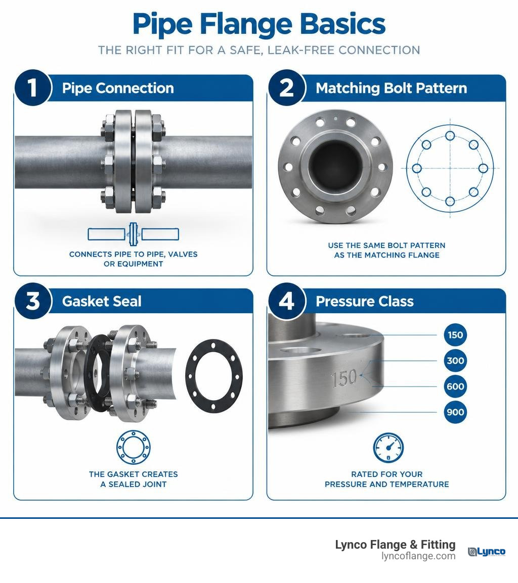
Easy pipe flange word list:
Primary Pipe Flange Types and Design Variations
In any industrial processing facility, piping systems must handle high pressures, fluctuating temperatures, and aggressive chemicals without leaking. Flanges provide the structural integrity required to secure these runs while maintaining the flexibility to disassemble sections whenever necessary. Gaining a complete understanding of the crucial purpose of pipe flanges helps engineering teams design safer, more efficient systems.
Each design variation addresses specific mechanical stresses, assembly constraints, or maintenance needs. Learning what are the different types of flanges for piping allows you to select the right configuration for your specific operating environment.
| Flange Type | Typical Attachment Method | Pressure Capability | Primary Application | Key Advantage |
|---|---|---|---|---|
| Weld Neck | Butt weld to pipe end | High to extreme (Class 150–2500) | Severe duty, cyclic loading, thermal extremes | Superior stress distribution via tapered hub |
| Slip-On | Fillet weld inside and outside | Low to moderate (Class 150–300) | Utility lines, non-critical process piping | Lower initial component cost and easy alignment |
| Blind | Bolted to mating flange face | Matches mating flange class | End-of-line isolation, hydrotesting | Safe pressure containment with cleanout access |
| Threaded | Screwed connection (NPT/BSPT) | Low to moderate | Hazardous welding zones, utility lines | No hot work or field welding required |
| Socket Weld | Fillet weld on outer hub | Moderate to high (Class 150–1500) | Small-bore lines (2″ and smaller) | Smooth interior bore with low flow resistance |
| Lap Joint | Slips over pipe; pairs with stub end | Low to moderate | Systems needing frequent dismantling | Easy bolt hole alignment via rotating flange ring |
Slip-On vs Weld Neck Pipe Flange Applications
The choice between slip-on and weld neck styles often comes down to mechanical stress and operational severity. A slip-on flange slides directly over the outer diameter of the pipe. Welders secure it by applying two fillet welds: one around the exterior hub and one inside the flange bore near the face. Because it lacks a tapered hub, stress concentrations remain localized near the welds. This makes slip-on flanges ideal for low-pressure utilities, water cooling lines, and construction environments where rapid fit-up keeps labor costs down.
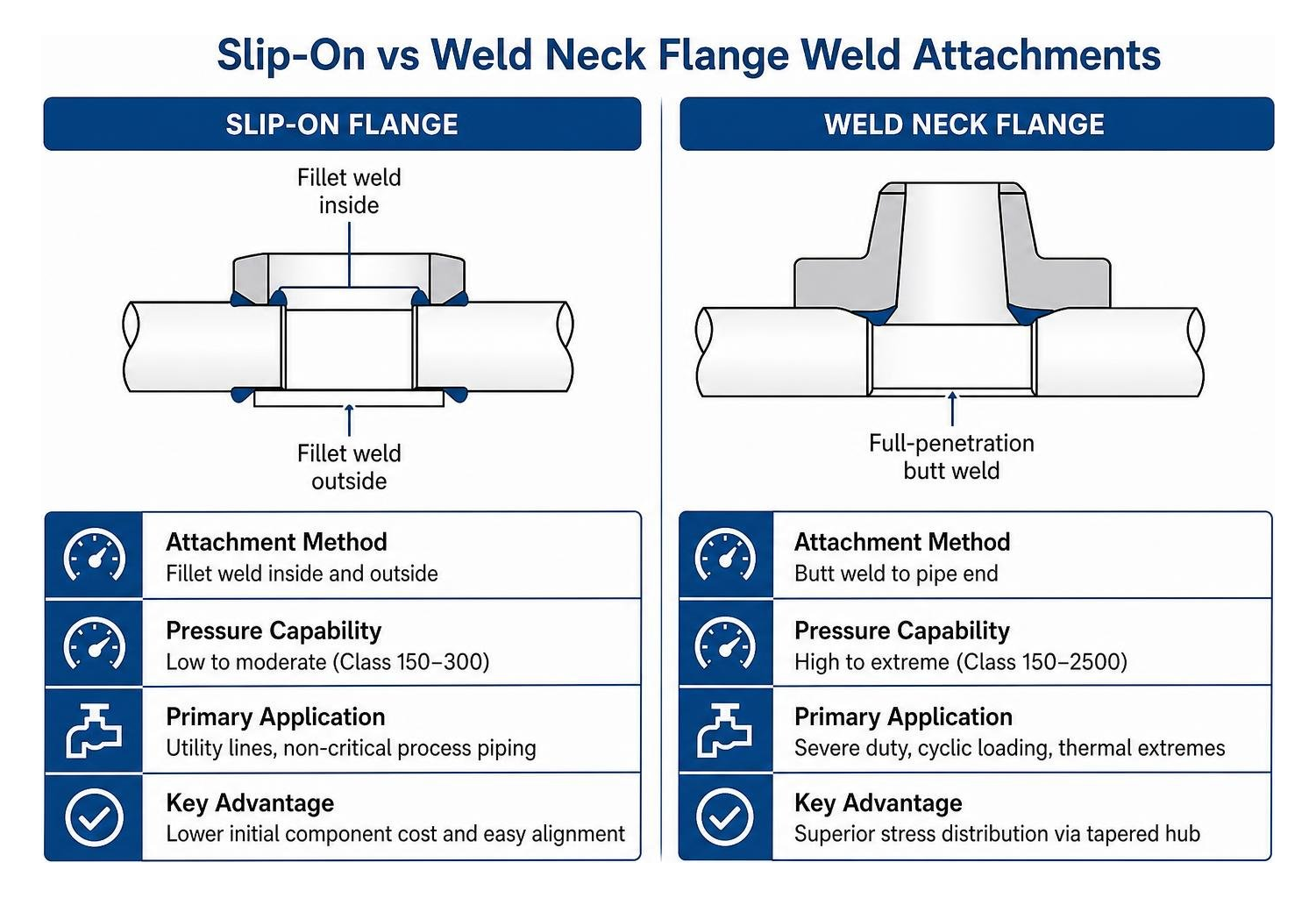
By contrast, having weld neck flanges explained reveals why they are standard across critical refinery and chemical infrastructure. A weld neck flange features a long, smooth, tapered transition hub that butt-welds directly to the matching schedule of the pipe. This full-penetration butt weld transfers mechanical loads directly to the pipe wall, minimizing localized stress risers. When an installation faces thermal cycling, severe vibration, water hammer, or elevated pressures up to Class 2500, weld neck fittings provide unmatched structural resilience.
Blind Flanges, Threaded Hubs, and Flat Base Options
Not all flanges feature open passages for fluid transport. A blind flange is a solid disc drilled with standard bolt holes. Operators use them to blank off pipe ends with blind flanges during system construction, maintenance outages, and pressure testing. When a line needs isolation, a blind flange serves as a dependable barrier that can be unbolted quickly once downstream work is finished.
Threaded flanges (or screwed flanges) feature an internal thread profile that screws directly onto an externally threaded pipe. Because they require no welding, they provide a reliable option for low-pressure utilities and volatile environments where open flames are prohibited.
For structural fabrication, handrails, architectural posts, and machine mounting, flat base flanges and floor flanges provide rigid anchoring:
- Flat Base Flanges (Hole-Free): Blank, un-machined steel discs with a center collar (such as a plain steel flat base flange designed for 1-1/4″ pipe with a 1.66″ outside diameter). These allow fabricators to drill custom bolt circles on-site to match legacy machinery mounts.
- Pre-Drilled Floor Flanges: Cast or forged discs featuring pre-drilled countersunk mounting holes, commonly made from black or galvanized malleable iron for bolting to concrete floors, walls, and structural steel.
Flange Standards, Pressure Classes, and Connection Specifications
Piping systems around the world rely on standardized dimensioning frameworks to ensure fittings, valves, and gaskets mate without leaks. Having flange standards explained ANSI ASME and more allows engineers to choose components that match operating pressures and regional codes.
Reviewing the primary types of valve end connections shows that flange dimensions are governed by international organizations. The American Society of Mechanical Engineers (ASME) sets standards in North America under ASME B16.5 (for sizes up to 24″ NPS) and ASME B16.47 (for large-diameter lines). In Europe and international markets, the Deutsches Institut für Normung (DIN) and European Norm (EN 1092-1) define metric flange criteria.
Matching Pipe Flange Dimensions and Pressure Ratings
A flange’s pressure class defines the maximum allowable working pressure across a range of temperatures. As fluid temperatures climb, the structural strength of the metal decreases, requiring pressure derating. Standard ASME pressure classes include:
- Class 125
- Class 150
- Class 300
- Class 400
- Class 600
- Class 900
- Class 1500
- Class 2500
A Class 300 flange is rated for working pressures well above 300 psi at ambient temperatures, but its allowable pressure drops steadily as process temperatures rise.
DIN flanges use nominal pressure designations (PN ratings) measured in bar:
- PN10 (10 bar)
- PN16 (16 bar)
- PN25 (25 bar)
- PN40 (40 bar)
- PN100 (100 bar maximum pressure)
Because ASME and DIN bolt circles, bolt hole counts, and overall diameters differ, they cannot be bolted together directly without custom transition spools. Checking what are the standard sizes of pipe flanges ensures that your replacement parts match the bolt circle diameter and schedule thickness of the existing line.
Thread Profiles and Sanitary Connection Types
For threaded and specialty lines, understanding pipe and pipe fittings connection types helps prevent thread galling and joint failures. Threaded flanges rely on three primary thread geometry standards:
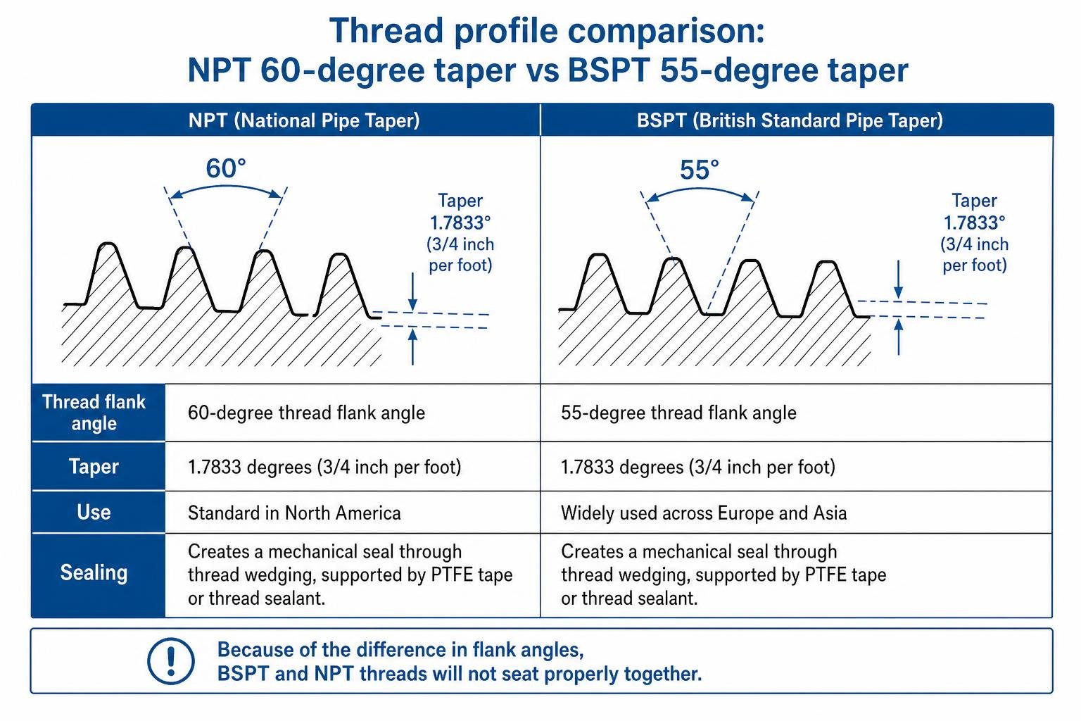
- National Pipe Taper (NPT): Standard in North America, featuring a 60-degree thread flank angle and a taper of 1.7833 degrees (3/4 inch per foot). The thread pitch scales with nominal diameter: 1/4″ and 3/8″ fittings use 18 threads per inch (TPI), 1/2″ and 3/4″ fittings use 14 TPI, and 1″ fittings use 11.5 TPI. The tapered profile creates a mechanical seal through thread wedging, supported by PTFE tape or thread sealant.
- British Standard Pipe Taper (BSPT): Widely used across Europe and Asia, featuring a 55-degree thread flank angle and the same 1.7833-degree taper. Because of the difference in flank angles, BSPT and NPT threads will not seat properly together.
- British Standard Pipe Parallel (BSPP): A straight, non-tapered thread design. BSPP connections do not seal along the threads; they rely on bonded seal washers, O-rings, or flat elastomeric gaskets compressed against a machined shoulder.
In hygienic processing sectors like food, dairy, beverage, and pharmaceuticals, standard threaded and flanged connections present contamination risks because fluid can collect inside gaps. These plants use clamp-type sanitary flanges (such as Tri-Clamp fittings). These sanitary connections feature smooth, crevice-free ferrules compressed over an elastomeric gasket using an external hinged mechanical clamp. This design eliminates dead legs and supports clean-in-place (CIP) and steam-in-place (SIP) sterilization cycles.
Flange Facing Designs, Gaskets, and Proper Installation
The sealing face of a flange dictates how compressive bolt loads are transferred to the gasket material, determining the joint’s overall leak resistance.

Raised Face vs Ring-Type Joint Sealing Mechanisms
Selecting the proper face design depends on your line pressure, process media, and pipe material:
- Flat Face (FF): The entire mating surface lies in the same plane as the bolt circle. Flat face designs are standard on cast iron equipment, bronze valves, and low-pressure utility systems. Using flat face flanges ensures that bolt torque does not generate bending moments that could crack brittle cast iron casings.
- Raised Face (RF): Features a concentrated circular pad raised above the bolt circle (typically 0.06 inches high for Class 150/300 and 0.25 inches for Class 600 and above). Reviewing raised vs flat faced flanges and their uses shows that this raised platform focuses bolt clamping force directly onto the gasket, providing high sealing stress. The face is machined with phonographic or concentric serrations (125–250 micro-inches Ra) that bite into sheet or spiral-wound gaskets.
- Ring-Type Joint (RTJ): Features a precision-machined trapezoidal or oval groove cut directly into the flange face. A solid metal ring gasket (soft iron, 304, or 316 stainless steel) seats inside this groove. When bolts are torqued, the metal gasket yields plastically within the groove, creating a durable metal-to-metal seal. RTJ flanges are standard in high-pressure oil and gas production exceeding Class 600 or temperatures above 800°F.
Our high pressure flange gasket selection guide explains how gasket material selection, from compressed non-asbestos fiber to graphite-filled spiral-wound gaskets, must match the flange face profile.
Gasket Placement and Bolt Torquing Protocols
Achieving a leak-free joint requires disciplined installation practices. Learning how to properly install flanges minimizes safety hazards and reduces downtime.
- Inspection and Cleaning: Flange faces must be clean and free of scale, corrosion, old gasket residue, and deep radial scratches.
- Alignment: Flange faces must be parallel, and bolt holes must align without using excessive force that could introduce residual bending stress.
- Two-Stage Bolt Insertion: Thread the bottom half of the flange bolts through the lower holes first. This creates a cradle that supports the gasket centrally between the faces.
- Gasket Positioning: Slide the gasket into place between the faces. Never use liquid gasket compounds or grease on spiral-wound or elastomeric gaskets unless specified by the manufacturer.
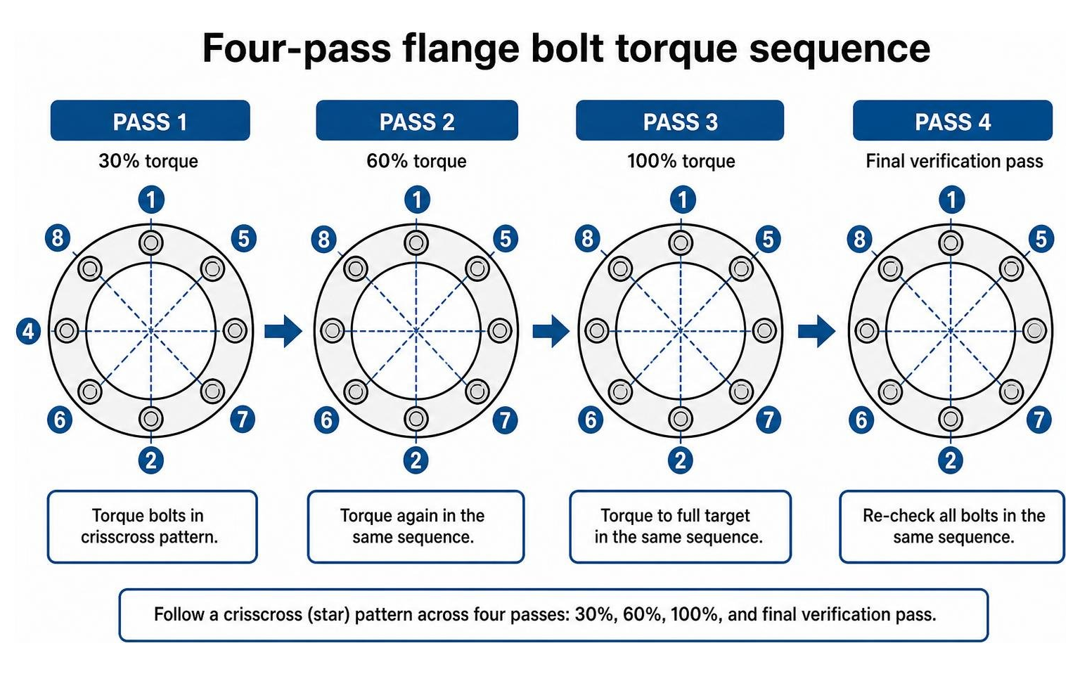
- Cross-Pattern Torquing: Following our guide on how to properly torque flanges, apply torque evenly using a star (crisscross) pattern. Torque the bolts across four sequential passes:
- Pass 1: Tighten bolts to 30% of target torque.
- Pass 2: Tighten bolts to 60% of target torque.
- Pass 3: Tighten bolts to 100% of target torque.
- Pass 4: Perform a final rotational pass at 100% target torque to ensure balanced gasket compression.
Uneven bolt loading and flange misalignment remain the primary answers to why do flanges leak. Systematic torquing ensures uniform gasket crush, eliminating leak paths.
Material Selection, Alloy Grades, and Safety Considerations
Flange materials must match the metallurgical properties of the attached pipe while resisting internal corrosion, mechanical fatigue, and ambient environmental exposure.
| Material Group | Common Specification | Typical Temperature Range | Corrosion Resistance | Common Industrial Application |
|---|---|---|---|---|
| Forged Carbon Steel | ASTM A105 / A350 LF2 | -20°F to 800°F (-50°F for LF2) | Moderate; requires coatings | General oil, gas, steam, and hydrocarbon refining |
| Austenitic Stainless | ASTM A182 F316 / F316L | -320°F to 1000°F | High; resists chlorides and acids | Chemical processing, marine, pharmaceutical |
| Duplex Stainless | ASTM A182 F51 / 2205 | -50°F to 550°F | Superior pitting/crevice resistance | Offshore platforms, subsea flowlines, desalination |
| Super Duplex | ASTM A182 F53 / 2507 | -50°F to 550°F | Extreme; PREN > 42 | High-chloride oilfield injection, brackish chemicals |
| Malleable Iron | ASTM A197 (Galv / Black) | -20°F to 350°F | Low to Moderate (Galvanized) | Low-pressure gas, fire protection, domestic water |
Understanding the process of choosing the right flange material for harsh oil and gas environments ensures long-term operational integrity and regulatory compliance.
Stainless Steel, Duplex, and Corrosion-Resistant Alloys
In corrosive service, 316 and 316L austenitic stainless steel provide excellent resistance to atmospheric moisture, organic acids, and moderate chlorides. The low-carbon variant (316L) resists carbide precipitation during welding, preserving corrosion resistance throughout heat-affected zones.
For more aggressive offshore and chemical environments, our guide comparing duplex vs super duplex flanges explains how mixed austenitic-ferritic microstructures provide twice the mechanical yield strength of standard stainless steels along with exceptional resistance to stress corrosion cracking. The wide range of benefits of using stainless steel flange fittings includes reduced wall thickness requirements, extended service life, and lower maintenance costs.
Structural and Utility Materials: Malleable Iron and Carbon Steel
For general utility lines and architectural assemblies, cast and forged irons remain cost-effective solutions:
- ASTM A105 Forged Carbon Steel: The standard material for high-pressure industrial piping. It offers high tensile strength and weldability, though it requires painting or coating to prevent external rust.
- Black Malleable Iron: Commonly used for residential and commercial natural gas lines, closed-loop hydronic heating, and industrial structural pipe assemblies.
- Galvanized Malleable Iron: Coated with a protective zinc layer via hot-dip galvanization, making it suitable for non-potable and potable water distribution, drainage systems, and outdoor handrail mounting.
Safety and Regulatory Warnings
When buying and handling raw steel, malleable iron, or plated pipe fittings, safety regulations like California’s Proposition 65 require manufacturers and distributors to notify purchasers if products contain trace elements such as lead, nickel, or hexavalent chromium compounds. Always consult product safety data sheets (MSDS/SDS) and use proper protective equipment when cutting, grinding, or welding steel fittings.
Frequently Asked Questions About Flange Specifications
How do I accurately match a replacement flange to an existing pipe?
To match an existing flange without original documentation, collect four measurements:
- Nominal Pipe Size (NPS): Measure the interior bore of the pipe or its outside diameter (for example, a 1-1/4″ nominal pipe has an outside diameter of 1.66 inches).
- Outer Flange Diameter (OD): Measure the total width across the outside edge of the flange.
- Bolt Hole Count and Diameter: Count the total number of bolt holes and measure their diameter.
- Bolt Circle Diameter (BCD): Measure the distance from the center of one bolt hole across to the center of the opposite bolt hole through the flange centerline.
Once you have these dimensions, compare them against ASME B16.5 or DIN dimension tables to identify the matching pressure class (such as Class 150 vs Class 300).
What is the primary difference between flanged and threaded pipe connections?
The main differences lie in mechanical strength, pressure capability, line size, and ease of maintenance:
- Flanged Connections: Utilize a bolted assembly clamping a gasket between two mating faces. They support large pipe diameters (from 1/2″ up to 60″+), operate across all pressure classes (up to Class 2500), and allow quick disassembly for cleaning and inspection.
- Threaded Connections: Rely on male-to-female thread engagement, making them suitable primarily for small-bore piping (2 inches and smaller) and low-to-medium pressure utility lines. They can be difficult to dismantle in long runs without installing dedicated pipe unions.
Why are blind flanges critical during pipeline maintenance and inspection?
Blind flanges provide a positive mechanical pressure barrier that isolates downstream piping. Unlike an inline isolation valve, which can leak past its seat or be opened by accident, a blind flange forms an absolute physical seal. This allows maintenance teams to hydrotest, inspect, clean, or extend upstream pipe segments safely while the rest of the facility remains operational.
Conclusion
Selecting the right pipe flange requires balancing mechanical loads, pressure ratings, material compatibility, and gasket sealing performance. Whether your application calls for high-pressure weld neck flanges in a refinery unit or threaded malleable iron fittings for utility lines, matching every component to recognized industry standards is essential for safe, reliable operation.
At Lynco Flange & Fitting, based in Houston, Texas, our engineering-focused sales team provides direct technical guidance, large on-hand inventories, and ISO-compliant quality control. We supply standard, forged, and custom industrial fittings tailored to the oil & gas, marine, power, and construction sectors. Partner with a trusted industrial flange distributor to find the right flange solutions for your upcoming piping projects.