Class 2500 Flange Dimensions in mm: The Key Measurements
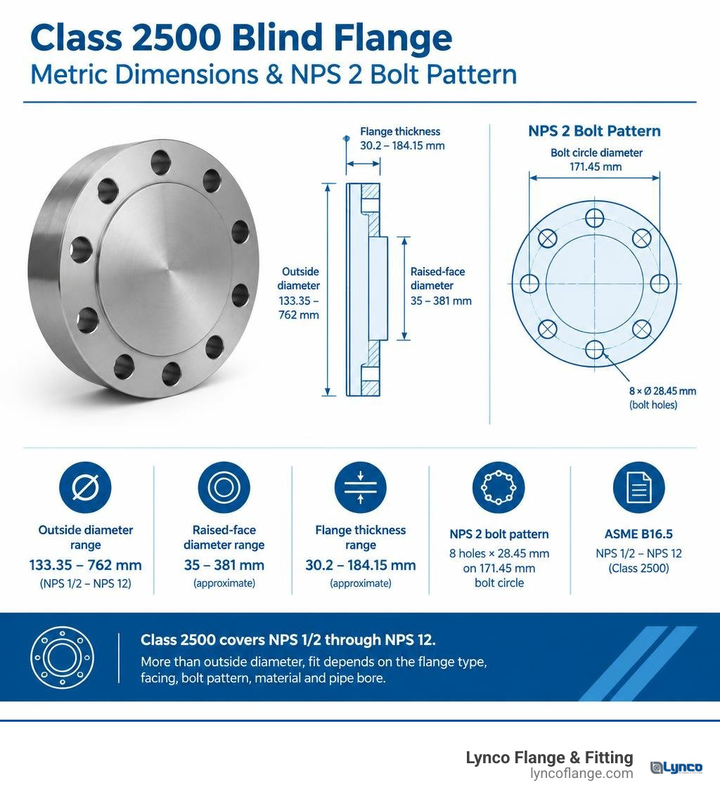
For raised-face blind flanges, class 2500 flange dimensions in mm range from 133.35 mm outside diameter at NPS 1/2 to 762 mm at NPS 12. Their raised-face diameters are about 35 mm and 381 mm, respectively, while flange thickness ranges from about 30.2 mm to 184.15 mm. Bolt patterns change with size: an NPS 2 flange has eight 28.45 mm holes on a 171.45 mm bolt circle.
These are ASME B16.5 dimensions, but fit depends on more than outside diameter. Check the flange type, facing, bolt pattern, material, and pipe bore before ordering. Class 2500 covers NPS 1/2 through NPS 12.
I’m Lance Vanover, CEO of Lynco Flange & Fitting, with 26 years of experience in industrial flange and fitting operations. I’ll walk through class 2500 flange dimensions in mm with the fit and handling details buyers need to verify.
ASME B16.5 Standard Overview and Class 2500 Pressure-Temperature Scope
When piping engineers design high-pressure containment systems, Class 2500 represents the pinnacle of standard flanged connections. Governed by the ASME B16.5 standard specifications, this rating designation is engineered to withstand extreme pressures and thermal cycles found in severe-service environments like upstream oil and gas manifolds, subsea tie-ins, and supercritical steam systems.
Unlike lower pressure classes (Class 150 through 1500) that extend up to NPS 24 (DN 600) under standard sizing rules, ASME B16.5 restricts the Class 2500 rating designation strictly to nominal pipe sizes from NPS 1/2 (DN 15) through NPS 12 (DN 300). Beyond NPS 12, the massive wall thicknesses and severe bolt preloads require custom engineering under ASME Section VIII rules rather than standard catalog piping components.
To maintain structural integrity under extreme hoop stress and thermal expansion, material selection is tightly controlled. Class 2500 components are forged or cast from high-yield carbon steels (ASTM A105, ASTM A350 LF2 for low-temperature service) or alloy and stainless steels (ASTM A182 grades F11, F22, F316/316L, and F51 duplex). Plate materials are permitted exclusively for blind flanges and select reducing flanges.
Understanding flange standards and pressure ratings requires evaluating how allowable working pressures diminish as operating temperatures rise. Consider the impact of temperature and pressure on flange and fitting selection: while a Class 2500 carbon steel flange can handle cold working pressures up to roughly 425 bar (6170 psi) at ambient temperatures, its working ceiling drops significantly when operating at 400°C.
| Nominal Pipe Size (NPS / DN) | Pressure Class | Outside Diameter (mm) | Flange Thickness (mm) | Bolt Circle Diameter (PCD in mm) | Number of Bolts |
|---|---|---|---|---|---|
| NPS 2 (DN 50) | Class 150 | 152.40 | 19.05 | 120.65 | 4 |
| NPS 2 (DN 50) | Class 300 | 165.10 | 22.35 | 127.00 | 8 |
| NPS 2 (DN 50) | Class 600 | 165.10 | 31.75 | 127.00 | 8 |
| NPS 2 (DN 50) | Class 2500 | 234.95 | 50.80 | 171.45 | 8 |
| NPS 6 (DN 150) | Class 150 | 279.40 | 25.40 | 241.30 | 8 |
| NPS 6 (DN 150) | Class 300 | 317.50 | 36.58 | 269.75 | 12 |
| NPS 6 (DN 150) | Class 600 | 355.60 | 54.10 | 292.10 | 12 |
| NPS 6 (DN 150) | Class 2500 | 482.60 | 107.95 | 368.30 | 8 |
As demonstrated in the comparison table above, Class 2500 flanges feature significantly larger outside diameters and thicknesses compared to lower pressure classes for the exact same nominal pipe bore.
Comprehensive Class 2500 Flange Dimensions in mm Reference
Navigating metric dimensional data for high-pressure industrial flanges requires checking every geometric parameter: outside diameter (OD), total thickness (C), raised face diameter (d), hub diameters, and drilling templates. While ASME B16.5 publishes dimensional data in both metric and imperial units, standard metric callouts round dimensions to clean fractions while maintaining tight machining tolerances per ASME standards.

When reviewing what are the standard sizes of pipe flanges, a critical geometric distinction of Class 2500 raised face (RF) flanges is their raised face height. While Class 150 and Class 300 flanges feature a standard 1.60 mm (1/16-inch) raised face, Class 2500 flanges incorporate a heavy 6.40 mm (1/4-inch) raised face across all nominal diameters from NPS 1/2 through NPS 12.
Weld Neck Class 2500 Flange Dimensions in mm and Bore Schedules
Weld Neck (WN) flanges are the primary choice for severe Class 2500 services. Their tapered hub transfers stress directly into the connected heavy-wall pipe, minimizing stress concentrations at the base of the flange.
Because Class 2500 piping systems operate at elevated pressures, the mating pipe wall thicknesses are substantial, typically requiring Schedule 80, Schedule 160, or Double Extra Strong (XXS) piping. When ordering weld neck flanges, specifying the precise inside bore diameter is mandatory to ensure smooth internal flow transitions and prevent localized erosion.
| Nominal Pipe Size (NPS / DN) | Outside Diameter (mm) | Flange Thickness (mm) | Total Length Thru Hub (mm) | Hub Diameter at Base (mm) | Sch 40 Bore (mm) | Sch XXS Bore (mm) | Approx. Net Weight (kg) |
|---|---|---|---|---|---|---|---|
| 1/2″ (15 mm) | 133.35 | 30.23 | 73.15 | 42.93 | 15.80 | 6.40 | 3.13 |
| 3/4″ (20 mm) | 139.70 | 31.75 | 79.25 | 50.80 | 20.93 | 11.07 | 4.08 |
| 1″ (25 mm) | 158.75 | 34.93 | 88.90 | 57.15 | 26.64 | 15.24 | 5.90 |
| 1-1/4″ (32 mm) | 184.15 | 38.10 | 95.25 | 66.55 | 35.05 | 22.76 | 9.07 |
| 1-1/2″ (40 mm) | 203.20 | 44.45 | 111.25 | 76.20 | 40.89 | 27.94 | 13.61 |
| 2″ (50 mm) | 234.95 | 50.80 | 127.00 | 95.25 | 52.50 | 38.18 | 16.09 |
| 2-1/2″ (65 mm) | 266.70 | 57.15 | 142.75 | 114.30 | 62.71 | 44.98 | 26.31 |
| 3″ (80 mm) | 304.80 | 66.55 | 168.15 | 133.35 | 77.93 | 58.42 | 40.82 |
| 4″ (100 mm) | 355.60 | 76.20 | 190.50 | 165.10 | 102.26 | 80.06 | 63.50 |
| 5″ (125 mm) | 422.15 | 92.20 | 228.60 | 203.20 | 128.19 | 103.20 | 113.40 |
| 6″ (150 mm) | 482.60 | 107.95 | 273.05 | 234.95 | 154.05 | 124.41 | 140.57 |
| 8″ (200 mm) | 552.45 | 127.00 | 317.50 | 279.40 | 202.72 | 174.63 | 244.94 |
| 10″ (250 mm) | 673.10 | 165.10 | 419.10 | 342.90 | 254.51 | 215.90 | 430.91 |
| 12″ (300 mm) | 762.00 | 184.15 | 463.55 | 406.40 | 303.23 | 257.18 | 566.01 |
Class 2500 Flange Dimensions in mm for Blind and Slip-On Flanges
Blind flanges act as pressure barriers for line termination and pressure vessel testing, requiring massive solid steel cross-sections to prevent deflection under thousands of pounds of hydrostatic pressure. Engineers referencing the ANSI Class 2500 blind flange dimensional datasheet will find that the thickness matches or exceeds corresponding weld neck flanges.
Slip-On (SO) flanges slide directly over the outer pipe diameter before being fillet welded at both the hub and interior pipe end. Because high cyclic stress can fatigue fillet welds, slip-on designs are restricted in severe Class 2500 service, but remain widely used in specific high-pressure utility lines. Learn more about the different types of flanges for piping to choose between blind, slip-on, and butt-weld connections.
| Nominal Size (NPS / DN) | Outside Diameter (OD mm) | Blind Flange Thickness (mm) | Blind Weight (kg) | Slip-On Bore Diameter (mm) | Slip-On Length Thru Hub (mm) | Slip-On Base Hub (mm) |
|---|---|---|---|---|---|---|
| 1/2″ (15 mm) | 133.35 | 30.23 | 3.18 | 22.35 | 39.62 | 42.93 |
| 3/4″ (20 mm) | 139.70 | 31.75 | 4.54 | 27.69 | 42.93 | 50.80 |
| 1″ (25 mm) | 158.75 | 34.93 | 5.44 | 34.54 | 47.75 | 57.15 |
| 1-1/4″ (32 mm) | 184.15 | 38.10 | 8.16 | 43.18 | 52.32 | 66.55 |
| 1-1/2″ (40 mm) | 203.20 | 44.45 | 11.34 | 49.53 | 60.45 | 76.20 |
| 2″ (50 mm) | 234.95 | 50.80 | 17.69 | 61.98 | 69.85 | 95.25 |
| 2-1/2″ (65 mm) | 266.70 | 57.15 | 25.40 | 74.68 | 79.25 | 114.30 |
| 3″ (80 mm) | 304.80 | 66.55 | 39.01 | 90.68 | 92.20 | 133.35 |
| 4″ (100 mm) | 355.60 | 76.20 | 60.33 | 116.08 | 107.95 | 165.10 |
| 5″ (125 mm) | 422.15 | 92.20 | 101.15 | 143.76 | 130.30 | 203.20 |
| 6″ (150 mm) | 482.60 | 107.95 | 156.49 | 170.69 | 152.40 | 234.95 |
| 8″ (200 mm) | 552.45 | 127.00 | 241.77 | 221.49 | 177.80 | 279.40 |
| 10″ (250 mm) | 673.10 | 165.10 | 464.93 | 276.35 | 228.60 | 342.90 |
| 12″ (300 mm) | 762.00 | 184.15 | 664.06 | 327.15 | 254.00 | 441.45 |
Threaded and Lap Joint Flange Dimensional Specifications
Threaded and Lap Joint flanges provide specialized mechanical joint solutions under Class 2500 ratings. Threaded (screwed) flanges feature internal NPT (National Pipe Taper) threads conforming to ASME B1.20.1, offering weld-free assembly in explosive environments where hot work is prohibited. Thread lengths must accommodate full pipe thread engagement to prevent spiral pressure leakage, with minimum thread lengths extending from 28.45 mm on an NPS 1/2 flange up to 120.65 mm on an NPS 12 flange.
Lap Joint (LJ) flanges are paired with Type A Stub Ends. Because the backing flange is loose and rotates freely around the stub end, it provides fast bolt hole alignment during field installation. In high-pressure systems utilizing exotic alloys like Inconel or Monel, the backing lap joint flange can be produced from economical carbon steel while only the wetted stub end requires corrosion-resistant alloy forging. When reviewing factors to consider when selecting industrial flanges, ensure the corner fillet radius of the lap joint bore (ranging from 8.0 mm on NPS 1/2 to 12.7 mm on NPS 12) matches the outside radius of the mating stub end.
Metric Bolting Specifications and Pitch Circle Diameters for Class 2500
Bolt hole pattern engineering for Class 2500 connections is designed around massive clamping forces. Standard ASME B16.5 rules dictate that bolt holes are machined 1/8 inch (3.18 mm) larger than the nominal stud bolt diameter to permit clearance for thermal movement and hydraulic bolt tensioning tools.
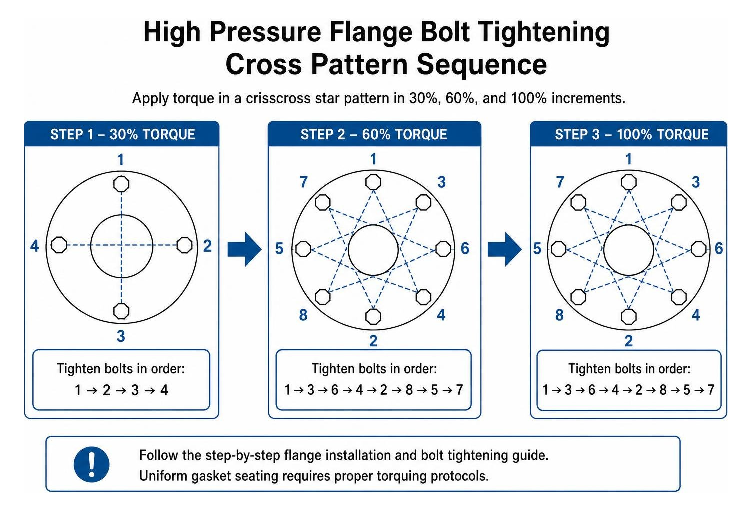
Uniform gasket seating requires proper torquing protocols. Follow the step-by-step flange installation and bolt tightening guide to apply torque in a crisscross star pattern in 30%, 60%, and 100% increments. Stud bolt lengths must account for flange thickness, gasket compression, heavy hex nut thickness, and tool puller thread engagement for tensioner tools.
| Nominal Size (NPS / DN) | Pitch Circle Diameter (PCD mm) | Number of Bolts | Bolt Hole Diameter (mm) | Stud Bolt Diameter (Inches) | Stud Bolt Length RF (mm) | Stud Bolt Length RTJ (mm) |
|---|---|---|---|---|---|---|
| 1/2″ (15 mm) | 88.90 | 4 | 22.35 | 3/4″ | 120.65 | 120.65 |
| 3/4″ (20 mm) | 95.25 | 4 | 22.35 | 3/4″ | 127.00 | 127.00 |
| 1″ (25 mm) | 107.95 | 4 | 25.40 | 7/8″ | 139.70 | 139.70 |
| 1-1/4″ (32 mm) | 130.05 | 4 | 28.45 | 1″ | 158.75 | 158.75 |
| 1-1/2″ (40 mm) | 146.05 | 4 | 31.75 | 1-1/8″ | 171.45 | 171.45 |
| 2″ (50 mm) | 171.45 | 8 | 28.45 | 1″ | 177.80 | 177.80 |
| 2-1/2″ (65 mm) | 196.85 | 8 | 31.75 | 1-1/8″ | 203.20 | 203.20 |
| 3″ (80 mm) | 228.60 | 8 | 34.93 | 1-1/4″ | 228.60 | 235.00 |
| 4″ (100 mm) | 273.05 | 8 | 41.15 | 1-1/2″ | 266.70 | 273.05 |
| 5″ (125 mm) | 323.85 | 8 | 47.75 | 1-3/4″ | 311.15 | 317.50 |
| 6″ (150 mm) | 368.30 | 8 | 53.85 | 2″ | 355.60 | 368.30 |
| 8″ (200 mm) | 438.15 | 12 | 53.85 | 2″ | 393.70 | 406.40 |
| 10″ (250 mm) | 539.75 | 12 | 66.55 | 2-1/2″ | 495.30 | 514.35 |
| 12″ (300 mm) | 619.25 | 12 | 73.15 | 2-3/4″ | 546.10 | 565.15 |
Ring Type Joint (RTJ) Gasket Groove Dimensions and Facing Details
In severe Class 2500 service, Ring Type Joint (RTJ) facings are often chosen over Raised Face (RF) configurations. RTJ connections use a precision-machined metallic ring gasket (octagonal or oval cross-section) seated into an annular groove on the flange face. As the heavy studs are tightened, the metal gasket yields plastically within the groove, creating a leak-tight metal-to-metal seal capable of withstanding extreme cyclic pressures.
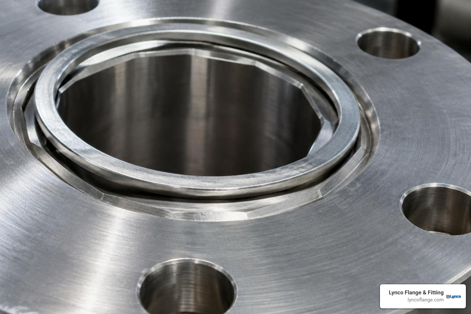
When consulting our pipe flange specifications 101 guide, pay close attention to RTJ ring numbers. Class 2500 RTJ grooves are designated with standardized ASME “R” numbers ranging from R13 up to R60. The groove depth (E) and groove width (F) must be machined to mirror finishes (typically Ra 1.6 μm or 63 microinches) to ensure proper gasket sealing without scoring the contact faces.
| Nominal Size (NPS / DN) | RTJ Ring Number | Pitch Diameter of Ring & Groove (P mm) | Groove Width (F mm) | Groove Depth (E mm) | Raised Face Diameter (K mm) |
|---|---|---|---|---|---|
| 1/2″ (15 mm) | R13 | 42.88 | 8.74 | 6.35 | 65.02 |
| 3/4″ (20 mm) | R16 | 47.63 | 8.74 | 6.35 | 68.33 |
| 1″ (25 mm) | R18 | 60.33 | 8.74 | 6.35 | 82.55 |
| 1-1/4″ (32 mm) | R21 | 72.24 | 11.91 | 7.92 | 101.60 |
| 1-1/2″ (40 mm) | R23 | 82.55 | 11.91 | 7.92 | 114.30 |
| 2″ (50 mm) | R26 | 101.60 | 11.91 | 7.92 | 133.35 |
| 2-1/2″ (65 mm) | R28 | 111.13 | 13.49 | 9.53 | 149.35 |
| 3″ (80 mm) | R32 | 127.00 | 13.49 | 9.53 | 168.15 |
| 4″ (100 mm) | R38 | 158.75 | 16.66 | 11.13 | 203.20 |
| 5″ (125 mm) | R42 | 190.50 | 16.66 | 11.13 | 241.30 |
| 6″ (150 mm) | R47 | 228.60 | 19.84 | 12.70 | 279.40 |
| 8″ (200 mm) | R51 | 279.40 | 19.84 | 12.70 | 339.85 |
| 10″ (250 mm) | R55 | 342.90 | 30.18 | 17.48 | 425.45 |
| 12″ (300 mm) | R60 | 406.40 | 33.32 | 17.48 | 495.30 |
Frequently Asked Questions About Class 2500 Flange Metric Specifications
What is the standard raised face height for Class 2500 flanges in millimeters?
The standard raised face height for all ANSI/ASME B16.5 Class 2500 flanges is 6.40 mm (0.25 inches). This height remains constant across every size from NPS 1/2 through NPS 12. Unlike Class 150 and 300 flanges, which feature a 1.60 mm raised face, the 6.40 mm raised face provides the additional machining depth and mechanical clearance required for high-stress gasket compression.
Why are ASME B16.5 Class 2500 flanges limited to NPS 12?
ASME B16.5 sets the dimensional boundary for Class 2500 at NPS 12 (DN 300) due to structural and manufacturing limitations. Beyond a 300 mm nominal bore, the extreme wall thicknesses, forging weights (exceeding 600 kg), and bolt tensions required to contain 400+ bar pressures make standardized piping flanges impractical. For line sizes larger than 12 inches under Class 2500 conditions, piping engineers must design custom flanged nozzles under ASME Boiler and Pressure Vessel Code (BPVC) Section VIII, Division 1 or Division 2 rules.
How much does a 12-inch Class 2500 blind flange weigh in kilograms?
An ASME B16.5 12-inch (DN 300) Class 2500 blind flange has an approximate net weight of 664.06 kg (1464 lbs). Because of its 762.00 mm outside diameter and 184.15 mm solid steel thickness, handling and installation require dedicated crane rigging, certified lift lugs, and specialized hydraulic tensioning equipment.
Conclusion
Class 2500 flanges provide the structural strength and pressure containment required for critical industrial piping systems. When procuring components for severe-service installations, verifying every metric parameter—from hub profiles and schedule bore diameters to RTJ groove geometry—is essential for safe, leak-free operation.
At Lynco Flange & Fitting, we distribute a complete range of industrial flanges and pipe fittings, including weld neck, forged steel, and custom-machined components for the oil and gas, power, marine, aerospace, and construction sectors. Based in Houston, Texas, our engineering-focused sales team delivers technical guidance, ISO-compliant quality control, and deep inventory for fast solutions.
To explore our full range of standard and custom high-pressure components, review our comprehensive reference on common pipe flange sizes and industrial uses or contact our technical sales team for application guidance.